
User Manual

<11. CALIBRATION OF ISC (Inductive Conductivity)>
11-2
IM 12A01A02-01E 5th Edition : Oct. 31, 2013-00
NOTE
The standard instrument to be used in calibration with a process solution should always be
accurate. Yokogawa recommends that the Model SC72 pocket conductivity meter be used for
this purpose.
Where temperature compensation 1 (SC1) and temperature compensation 2 (SC2) have been
congured,theconguredtemperaturecompensationiseffectiveevenduringcalibration.
Therefore, the reading is the value converted to a conductivity value at the reference temperature
set in Temperature settings.
There are temperature compensation 1 (SC1) and temperature compensation 2 (SC2), but this
doesnotmeanthatcalibrationisrequiredtwice.ItmeansthateitherSC1orSC2temperature
compensation should be selected and calibration should be made once to obtain the cell
constant.ThecellconstantaftercalibrationcanbecheckedontheDetailscreen.
NOTE
Whenasensorisexchangedorreplaced,sensorwellnessdatashouldbereset.
When a sensor is replaced, the replacement can be recorded manually into a logbook. (Refer to
thegure9.8.)
l Cell constant
The center value of the cell constant of the ISC40 sensor is 1.88 cm
-1
. The nominal cell constants
of individual sensors are indicated on the cable markers and the actual installation can change
this factor. If there is less than 30 mm spacing between a sensor and holder, in-situ calibration is
necessarytomeetthespeciedaccuracies.
• If the sensor is installed in the stainless steel standard holder ISC40FFJ-S, the cell constant
isreducedbyapproximately7%;enteravalue7%smallerthanthevalueonthemarkerof
the sensor cable.
• If the sensor is installed in the polypropylene standard holder ISC40FFJ-P, the cell constant
isincreasedbyapproximately1%;enteravalue1%greaterthanthevalueonthesensor
cable marker.
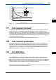
• Ifthesensorisinstalledinpipingthatislongintheaxialdirectionwiththecrosssection
as shown in Figure 11.3, the cell constant of the sensor installed in the piping (reference
data for a design center value of 1.88 cm
-1
) is as shown in Figure 11.3. A value obtained by
multiplying the value on the sensor cable marker and a value read from Figure 11.3 should
be entered.
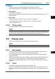
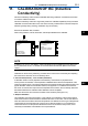
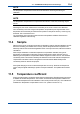
X= 30 mm (Min.)
XX
X
Figure 11.2 Sensor in calibration solution