
User Manual


<10. COMMISSIONING OF ISC (Inductive Conductivity)>
10-7
IM 12A01A02-01E 5th Edition : Oct. 31, 2013-00
Burn
Select the designated output in case of a fault from among Off, Low, and High. See “10.3 Error
conguration”tosettheoutput.
Off: Output depends on the measured value.
Low: Outputisxedto3.6mA(whenNoneissetinCommunicationsetup)
Outputisxedto3.9mA(whenHARTorPH201GisselectedinCommunicationsetup)
High:Outputisxedto22.0mA.
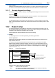
Damping time
Thisisthetimetakenforaresponsetoastepinputchangetoreach90%ofthenalvalue
(attenuation time). Set this time in sec.
l Simulate
Whenthisfunctionisselected,anoutputoftheinstrumentwillbeaxedcurrentvaluesetin%of
the output span. The output span range is -2.5% to 112.5% (3.6 mA to 22.0 mA).
When “Simulate” is selected, regardless of hold setting, the output is always simulated value.
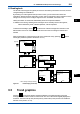
n CongureHold
OntheCongureHold,settingsareperformedtoholdofthemAoutputatapresetvalue.(Refer
to the section 11.7.) This is enabled only if “mA” is “Output.”
DuringtheCommissioningortheQuickSetup,themAoutputisautomaticallyheld.Thepreset
valuedependsonasettingonthe“Lastorxed”.
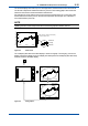
“Last”: The preset value is a value measured just before hold condition.
“Fixed”: Thepresetvalueisavaluesetinthe“FixedvaluemA”.
Whenthe“Fixed”isselected,setamAvalueinthe“FixedvaluemA”.
Selection on the “Hold during Calibration” decides to activate or deactivate the hold function
automatically during calibration.
“Enabled”: Activation of the automatic hold function
“Disabled”: Noautomaticholdfunction
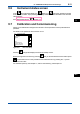
10.3 Errorconguration
InErrorconguration,congurethestatusesofvariouserrorcauses.
This allows the system to notify the user of the occurrence of an error according to the status
categoriesintheErrorconguration.
Select a status category from among Off, Warn. (Warning), and Fault.
“Fault”automaticallyperformsburn-out.WhenBurnhasbeensettoOff(10.2Outputsetup),only
the error message is displayed.
“Warn.” displays an error message.
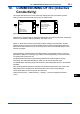
When selecting PH201G in the communication setting, make sure that the “Fail contact” setting
is appropriate.
The settable causes of errors are determined based on the settings of the Sensor setup and
Measurement setup, and a status category is set to the causes displayed in the Errors 1/3 to 3/3
screens.
ISC
10