
User Manual


<10. COMMISSIONING OF ISC (Inductive Conductivity)>
10-2
IM 12A01A02-01E 5th Edition : Oct. 31, 2013-00
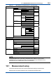
Table 10.1 Menu Structure and Default Values in “Commissioning”
Parameter Ref. sect.
Measurement setup Measurement 10.1.1
Conguresensor
Measuring unit 10.1.2
Cell constant (factory)
Temperature settings
Temp. element 10.1.3
Temp. compensation Compensation 10.1.4
Reference temp.
Method
Calibration settings Limits: Air adjust 10.1.5
c.c.
Timing: Step Range
Stabilization time
Calib.interval
Concentration Additional table 10.1.6
Unitfortable
Sensor diag. settings Process time: 10.1.7
Heat cycle:
Deneheatcycle
Output setup mA 10.2
Output
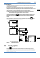
Process parameter
Setup
Linear
0 % value
100 % value
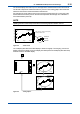
Table
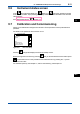
Burn
Dampingtime
Simulate Simulation perc.
CongureHold
Errorconguration 10.3
Logbookconguration 10.4
Advanced setup Settings 10.5.1
Tag 10.5.2
Passwords 10.5.3
Date/Time 10.5.4
Communication 10.5.5
HART
PH201G
Factory setup 10.5.6
Displaysetup Main display 10.6.1
Trend 10.6.2
Auto Return 10.6.3
Adjust contrast 10.6.4
MONITORdisplay 10.6.5
NOTE
Alltheparametersforthequicksetup(underlinedonesinTable10.1)arecrucialfor
measurement. If you change any of them, other parameters may be initialized. For the
parametersthatmayinitializeothervalues,seeAppendix3.
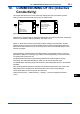
10.1 Measurement setup
This section describes how to set up various parameters relating to measurements.
Measurements are performed based on the measurement parameter setup.