
Manual

<1. Wiring and Installation>
5
IM 12A01A02-12E 4th Edition : Sep. 3, 2013-00
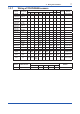
1.3.3 SC Measurement
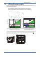
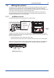
Contacting Conductivity, SC, sensors are connected to the module as follows:
11 +
-
V-
i-
Temp
V+
i+
12
13
14
15
16
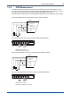
The above diagram shows wiring for 4-electrode conductivity sensors, such as SC42-SP34
large bore series. For 2-electrode conductivity sensors, such as SC42-SP36 small bore series,
jumpers must be installed between terminals 13-14 and between terminals 15-16, as shown in
the diagram below.
11 +
-
V-
i-
Temp
V+
i+
12
13
14
15
16
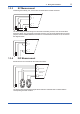
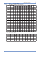
1.3.4 ISC Measurement
ISC40 sensors are connected to the module as follows:
11 +
-
Temp
Receive coil
Drive coil
12
13
17
15
16
14 Sensor shield
(internal)
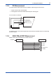
Thesensorsaresuppliedwithintegralcablesandeachindividualwireismarkedwiththe
corresponding terminal numbers.