
Manual

<1. Wiring and Installation>
9
IM 12A01A02-12E 4th Edition : Sep. 3, 2013-00
NOTE
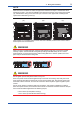
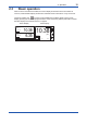
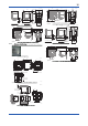
When two sensor modules are used, the upper-level module is for input 1 and the lower-level
moduleisforinput2.Foreaseofinstallation,rstwireinput2sensoronthelower-levelmodule
(A), and attach the wiring cover; then wire input 1 sensor on the upper-level module (B) and
replace the module wiring cover (C).
(A) (B) (C)
When all wiring is completed and all covers have been installed, the front cover can be closed
and the power can be switched on.
WARNING
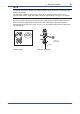
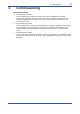
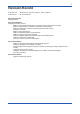
Whenoneofthemoduleshasbeenremovedandreplaced,makesureyoulockthemodule
securelyinplace.Conrmthatalllocking-tabs(includingforBLANKslots)arein“Locked”
positionbeforeyouclosethefrontpanel.Ifthelocking-tabsarein“Unlock”position,thefront
panelmaybeinterferedwithlocking-tabs.
Unlock
Lock
WARNING
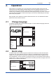
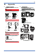
Do not tighten up four front panel screws one by one.
Eachfrontpanelscrewshouldbetightenedupintwotimesofscrewing.And,rstlythescrew
at the upper left should be screwed a bit, the next is at the lower right, third is at the upper right,
andfourthisatthelowerleft.Thesecondroundisthesamesequenceagaintotightenupfour
screws.
Do not use an electric screwdriver with high revolutions. If an electric screwdriver is used for
these front panel screws, the revolutions of the electric screwdriver should be less than 400 rpm.
Fourscrewsshouldbetightenedtothefollowingtorque;
0.8to0.9N•m(fortheplastichousing)
1.5to1.6N•m(forthestainlesssteelhousing)