User’s Manual Model FLXA21 2-Wire Analyzer Start-up Manual IM 12A01A02-12E This note is designed to assist with the installation of the FLXA21. This document should be used in conjunction with the User’s Manual of the FLXA21.
Toc-1 Model FLXA21 2-Wire Analyzer Start-up Manual IM 12A01A02-12E 4th Edition CONTENTS 1. 2. Wiring and Installation..................................................................................1 1.1 Installation site...................................................................................................... 1 1.2 Wiring the power supply...................................................................................... 2 1.3 Wiring the sensor.......................................
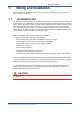
1. 1 <1. Wiring and Installation> Wiring and Installation Open the cover and remove the plastic inserts covering the modules. They will be reinstalled after the wiring is completed. 1.1 Installation site The FLXA21 is weatherproof and can be installed both inside and outside. It should, however, be installed as close as possible to the sensor to avoid long cable runs between the instrument and sensor.
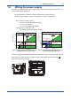
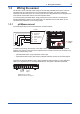
Wiring the power supply FLXA21 is a 2-wire transmitter and can be powered by a DC power supply of max. 40 VDC. The Power Supply voltage depends on: • The load resistance: impedance of electronic equipment: typically 250 Ohm • Number of input modules: 1-sensor measurement or 2-sensor measurement. One (1) Sensor module (1 input): 16 to 40 V DC (for pH/ORP, SC and DO) 17 to 40 V DC (for ISC) 21 to 40 V DC (SENCOM pH/ORP) Two (2) Sensor modules (2 inputs): 22.
1.3 3 <1. Wiring and Installation> Wiring the sensor The FLXA21 can be used with a wide range of commercially available sensor types, both from Yokogawa and other manufacturers. For more detailed information, refer to the respective instruction manual of the sensor. The sensor systems from Yokogawa fall into two categories; the ones that use a fixed cable and the ones with separate cables.
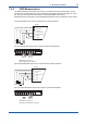
<1. Wiring and Installation> 1.3.2 4 ORP Measurement The ORP measurement uses the same sensor input module as the pH measurement. It is not uncommon to measure ORP as process variable and a pH Glass electrode as reference. This is the case with rH measurement and with pH compensated ORP measurement.
1.3.3 5 <1. Wiring and Installation> SC Measurement Contacting Conductivity, SC, sensors are connected to the module as follows: 11 + Temp 12 - 13 V14 i- 15 V+ 16 i+ The above diagram shows wiring for 4-electrode conductivity sensors, such as SC42-SP34 large bore series. For 2-electrode conductivity sensors, such as SC42-SP36 small bore series, jumpers must be installed between terminals 13-14 and between terminals 15-16, as shown in the diagram below.
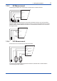
1.3.5 6 <1. Wiring and Installation> DO Measurement The input module for DO measurement is suitable for different types of DO sensors: i. Galvanic sensors like model DO30G ii. Polarographic sensors like HAMILTON’S Oxyferm and Oxygold The connection is as follows: 11 TC + 12 TC 16 15 + anode galvanic 13 - cathode galvanic 18 + anode polarographic 14 shield 17 - cathode polarographic The DO30G sensor comes with integral cable and the wires are labeled with the corresponding terminal numbers. 1.3.
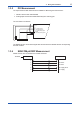
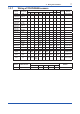
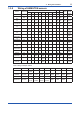
7 <1. Wiring and Installation> 1.3.7 Wiring of YOKOGAWA sensors Sensor Measurement DO30G FU20 /PH20/FU24 FU20 /PH20/FU24 FU20 /PH20/FU24 FU20-VP /FU24-VP FU20-VP/ FU24-VP FU20-VP/ FU24-VP ISC40 PR20/PR10 DO pH, pH & ORP, rH ORP pH Comp. ORP pH, pH & ORP, rH ORP pH Comp. ORP ISC pH SC21 pH SC24V SC25V pH pH pH Comp.
1.3.8 8 <1.
9 <1. Wiring and Installation> NOTE When two sensor modules are used, the upper-level module is for input 1 and the lower-level module is for input 2. For ease of installation, first wire input 2 sensor on the lower-level module (A), and attach the wiring cover; then wire input 1 sensor on the upper-level module (B) and replace the module wiring cover (C). (A) (B) (C) When all wiring is completed and all covers have been installed, the front cover can be closed and the power can be switched on.
<1. Wiring and Installation> 10 NOTE The special grommet is intended to be used to seal the multiple cables from the Yokogawa flow fittings such as FF20. The designated cables are WU20 sensor cables, which are approximately 5 mm (0.2”) in diameter, and K1500FV liquid earth cables, which are approximately 2.5 mm (0.1”) in diameter. For sensor systems using a single cable, like the FU20/FU24 and the PR10, PD20, PF20 and PS20, the standard gland will accommodate the cable adequately.
2. 11 <2. Operation> Operation When all wiring is completed, turn on the power to the instrument. Make sure that the LCD screen turns on, and then wait for the Quick Setup menu to be displayed. Follow the on-screen instructions for set-up and calibration. If the instrument is not configured correctly an error indicator may be displayed, or the measurement values displayed may be incorrect.
2.3 12 <2. Operation> Basic operation When 2 sensor modules are installed, the Home display shows both sensor information at one time, while the Main display will show the individual sensor information. If only one sensor is grayed out and disabled on the Main display. On the Home module is installed, the display, pressing the 1st sensor (top) information or the 2nd sensor (bottom) information causes the Main display of the selected sensor to appear. Home Display Main Display Tag:FLXA21–PH 25.
3. <3. Commissioning> 13 Commissioning QUICK SET-UP NOTES: a. pH measurement module Under “measurement “a selection is made for pH, ORP or pH&ORP. The selected measurement must be in accordance with the sensor wiring. When rH measurement is requested pH&ORP must be chosen on this level. The rH must then be selected in the commissioning menu. b. SC measurement module Under “measurement” a selection is made between Conductivity, Resistivity, Concentration or Concentration plus Conductivity.
4. 14 <3. Commissioning> Maintenance n Periodic maintenance The FLXA21 requires very little periodic maintenance, except to make sure the front window is kept clean in order to permit a clear view of the display and allow proper operation of the touchscreen. If the window becomes soiled, clean it using a soft damp cloth or soft tissue. To deal with more stubborn stains, a neutral detergent may be used.
15 Appendix u A1 A2 capabilities. install the cable glands. CAUTION inches). Unused cable entry holes must be sealed with cable glands including the supplied close up plugs. For sensor 1 cable For sensor 1 cable (For sensor 2 cable) A2.1 144 22.5 (For sensor 2 cable) 151 141 Uit: mm 80 44 For grounding cable 80 22.2 For sensor 1 cable 137 Stainless Steel Housing 4-M6 depth 5 (For sensor 2 cable) F0202.ai Cable gland diagram 26.5 26.5 24.7 Figure A.
16 Unit: mm 173 165 144 Pipe 50A (ø60.5) (205) 151 4-M6 * 13 Unit: mm 200 50 200 174 234.5 165 4-M6 * M8 U-bolt *: Tighten the four screws to a torque of 2 N•m. 220 FB4_07.ai Figure A.12 100 FB4_04.ai Figure A.7 184 144 70 100 *: Tighten the four screws to a torque of 2 N•m. Pipe mounting (Vertical) Pipe mounting (Horizontal) 15 50 For wall mounting 3-ø10 holes Pipe 50A (ø60.5) (214) 9 165 Unit: mm Unit: mm 200 199 144 184.
i Revision Record Manual Title : Model FLXA21 Two-wire Analyzer Start-up Manual Manual No. : IM 12A01A02-12E May 2010/1st Edition Newly published Aug. 2010/2nd Edition Followings are mainly revised; Addition of grounding terminal position on stainless housing with specific mountings Addition of plate position on stainless housing with specific coatings Addition of explanation of sleeve for grounding wire for plastic housing Correction of torques Addition of Note, Warning etc.