2940 AIR ADJUST RESIDUE MANAGER OPERATOR’S MANUAL PART IDENTIFICATION 2565-773_REV_C ● 03/2014 *Patent Pending YETTER MANUFACTURING CO. FOUNDED 1930 Colchester, IL 62326-0358 Toll free: 800/447-5777 309/776-3222 (Fax) Website: www.yetterco.com E-mail: info@yetterco.
FOREWORD You’ve just joined an exclusive but rapidly growing club. For our part, we want to welcome you to the group and thank you for buying a Yetter product. We hope your new Yetter products will help you achieve both goals-increase your productivity and increase your efficiency so that you may generate more profit. This operator’s manual has been designed into four major sections: Foreword, Safety Precautions, Installation Instructions and Parts Breakdown.
SAFETY A brief description of signal words that may be used in this manual: CAUTION: Used as a general reminder of good safety practices or to direct attention to unsafe practices. WARNING: Denotes a specific potential hazard. DANGER: Denotes the most serious specific potential hazard. SAFETY PRECAUTIONS You can make your farm a safer place to live and work if you observe the safety precautions given. Study these precautions carefully and insist that those working with you and for you follow them.
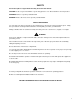
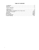
TABLE OF CONTENTS Introduction……….…………………………………………………………...2 Warranty….…………………………………….……………………………...2 Safety Information.…………………………………………………………....3 Table of Contents……….…………………………………………………….4 Bolt Torque………..….……………………………………………………….5 2940 Air Adjust Components, Kits, Accessories………………………..6-9 Installation Instruction….………..…….………………..…………..…..10-46 Operation…..……………………………...…………………………...…47-58 Maintenance….……………………………..…...……………………….59-65 Parts Identification…….…………...…………………..………….…......
BOLT TORQUE Mounting bolts and hardware All hardware used on the 2940 Air Adjust is Grade 5 unless otherwise noted. Grade 5 cap screws are marked with three radial lines on the head. If hardware must be replaced, be sure to replace it with hardware of equal size, strength and thread type. Refer to the torque values chart when tightening hardware. Important: Over tightening hardware can cause as much damage as when under tightening.
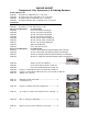
2940 AIR ADJUST Components, Kits, Accessories, & Ordering Numbers Residue Manager Kits 2940-001 Pneumatic Assembly with choice of wheel kit 2940-002 Pneumatic Narrow Assembly with choice of wheel kit 2940-003 Pneumatic CNH Assembly with choice of wheel kit 2940-004 Pneumatic CNH Narrow Assembly with choice of wheel kit Control Kits 2940-050 Pneumatic Compressor Kit 2940-053 Pneumatic Less Tank and Compressor Kit Air Lines and Wiring Kits For 2940-050 Kit 2940-065 8 Row—20’ wiring and tubing kit 2940-066 12
2940 AIR ADJUST Components, Kits, Accessories, & Ordering Numbers (CON’T) 2940-154 2940-155 30’ Dump Valve Cable Black---------------------------------------- 30’ Dump Valve Cable White 2940-156 2940-157 15’ Dump Valve Cable Black------------------------------------------ 15’ Dump Valve Cable White 2940-158 2940-159 2940-160 3” Y Harness Black Connector--------------------------------------- 3” Y Harness White Connector 5’ Dump Valve Cable White 2940-161 5’ Dump Valve Cable Black-----------------
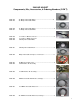
2940 AIR ADJUST Components, Kits, Accessories, & Ordering Numbers (CON’T) 2940-169 10’ Cab to Hitch Extension----------------------------------------------- 2940-170 2940-171 10’ Can Aux to Air Assembly Extension------------------------------ 30’ Can Aux to Air Assembly Extension 2940-336 Dump Valve------------------------------------------------------------------ PART NUMBER A B C DESCRIPTION 3/8 PUSH CONNECT ELBOW 1/8 NPT MALE----------------- 1/8 2940-337 NPT 3/8 PCT 8 2940-338 3/8 NPT 3/8 P
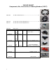
2940 AIR ADJUST PART NUMBER 2940-345 3/8" OD,TUBING, BLACK QTY (FT) 100 PACKAGE COIL PART NUMBER 2940-346 3/8" OD, TUBING, BLUE QTY (FT) 100 PACKAGE COIL 2940-357 Extreme Air Magnum Compressor Rebuild Kit 2940-367 3/8”OD 250PSI Working Pressure Tubing 25FT Roll 2940-390 Extreme Air Magnum Compressor with Filter Kit 2940-395 Filter Element/Compressor----------------------------------------- 2940-396 2940-430 Filter Pre-Cleaner-Compressor------------------------------------ 20FT CAN AUX to Ai
SYSTEM REQUIREMENTS POWER SUPPLY The 2940 system uses a switched power source. The 2940-153 will need connected to a switched power source. (Connector to the tractor not included) SWITCHED POWER SOURCE CONNECTOR PART #’S: JOHN DEERE P/N: RE67013 CNH P/N: 187103A1 FUSE PROTECTION To protect the Compressor Assembly from damage always ensure the integrity of the integrated 40 amp and/or 80 amp circuit breaker at the tractor cable where connected to the battery in case of short or over-circuit.
2940 AIR ADJUST SYSTEM INFORMATION The 2940 Air Adjust Residue Manager control system consists of five primary components and kits. These parts include; the Cab Controller, the Air Compressor Assembly, Residue Manager Kit, Tank Mounting Kit and the necessary Wires, Air Lines, and Fittings. CAB CONTROLLER____________________________________________________________ 2940-100 The Cab Controller will use the RAM mount provided for installation in cab.
2940 AIR ADJUST SYSTEM INFORMATION RESIDUE MANAGER__________________________________________________________ WIRE, LINES, AND FITTINGS KIT_____________________________________________ 12V-DC cables will be used to power the air compressor, cab control, and dump valves. Flexible tubing will be used to move air from the tank to each air bag.
2940 AIR ADJUST SYSTEM INFORMATION ________________________CAB CONTROLLER SERIAL #______________________ Serial # is located on the back of the Cab control. See photo below. Serial Number Location Serial # is located on the front of VDM in the compressor assembly. See photo below.
2940 AIR ADJUST ASSEMBLY GUIDE OUTLINE STEP 1: INSTALLING 2940-100 CONTROLLER Begin by installing the 2940 Air Adjust by mounting the 2940-100 Cab Controller and 2940-133 RAM Mount within the cab of the tractor. Position the Cab Controller within reach during operation without compromising safety or visibility from the cab. Route the 2940-152 cable from the hitch connecting point to the switch panel. Refer to page 15.
INSTALLING THE CAB CONTROLLER Step 1: Begin installing the 2940 Air Adjust controller once an adequate mounting location has been found, fix the base component of the 2940-113 Mounting Bracket in place. Connect the mount bracket to the rear of the controller. Step 2: Attach the male end 2 pin connector of the 2940-153 to the female end 2 pin connector on the 2940-100 cab controller.
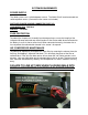
INSTALLING 2940 AIR COMPRESSOR ASSEMBLY Begin by mounting the 2940 Compressor: Step 1: Every planter/tractor combination will contain its own unique situations in regard to mounting the 2940 Compressor Assembly for clearance and accessibility. YOU SHOULD EXERCISE YOUR OWN BEST JUDGEMENT TO FIT YOUR SITUATION. Begin by locating a suitable mounting location for the compressor assembly. Placement of the compressor assembly will vary on the make and model of the planter.
INSTALLING 2940 COMPRESSOR ASSEMBLY 2940 AIR COMPRESSOR MOUNTING GUIDE 2940-085 mounting kit is designed for mounting to the 2 point cross hitch on the planter, or require greater elevation of the compressor for clearance reasons. The most common mounting location for larger planters will be on the draft bar. Use the 2940-086 mounting kit for situations that require mounting elsewhere on the planter than the hitch.
2940-101 External Lay Out A. LATCHES (2940-307) FOR CLOSING AIR COMPRESSOR HOUSING LID B. WHEEL TRACK DOWN PRESSURE PORT- ROUTE BLACK AIR TUBING FROM THE WT PORT TO THE DOWN PRESSURE DUMP VALVE ON CENTER ROWS OF THE PLANTER. THE DOWN PRESSURE PSI ON THE CENTER SECTION RESIDUE MANAGERS CAN BE ADJUSTED SEPARATELY FROM THE WING SECTION RESIDUE MANAGERS DOWN PRESSURE PSI. IF THE WT PORT IS NOT USED, INSTALL THE 2940-352 PLUG TO PREVENT AIR LOSS. C.
2940-101 Internal Lay Out A. B. C. D. E. F. G. H. I. J. K. L.
2940-101 Internal Lay Out A. B. C. D. E. F. G. H. I. J. K. L. M. N. O.
2940-103 2940-103 Compressor Control Module is an assembled unit, (less tank and compressor) that utilizes compressed air supplied by the OEM hydraulic compressor to operate the 2940 Air Adjust Residue Manager.
2940-103 External Lay Out A. WHEEL TRACK DOWN PRESSURE PORT- ROUTE BLACK AIR TUBING FROM THE WT PORT TO THE DOWN PRESSURE DUMP VALVE ON CENTER ROWS OF THE PLANTER. THE DOWN PRESSURE PSI ON THE CENTER SECTION RESIDUE MANAGERS CAN BE ADJUSTED SEPARATELY FROM THE WING SECTION RESIDUE MANAGERS DOWN PRESSURE PSI. IF THE WT PORT IS NOT USED, INSTALL THE 2940-352 PLUG TO PREVENT AIR LOSS. B.
2940-103 Internal Lay Out 24
Connecting Air Supply from Hydraulic Compressor to 2940-103 Compressor Control Module 2940-415 Water Separator Lay Out 25
INSTALLING 2940 AIR ADJUST RESIDUE MANAGER KITS READ BEFORE BEGINNING INSTALLATION ENGAGE THE CYLINDER STOPS ON THE PLANTER LIFT WHEELS TO “LOCK” THE PLANTER IN THE UP POSITION Installation overview: • Prior to installing check the freedom of motion of the row cleaner. 26 • The installation process should be done with the planter raised, half folded for transport, and the row units fully extended down.
INSTALLING 2940 AIR ADJUST RESIDUE MANAGER KITS READ BEFORE BEGINNING INSTALLATION ENGAGE THE CYLINDER STOPS ON THE PLANTER LIFT WHEELS TO “LOCK” THE PLANTER IN THE UP POSITION Installation overview: 1) Prior to installing check the freedom of motion of the row cleaner. 2) The installation process should be done with the planter raised, half folded for transport, and the row units fully extended down.
INSTALLING 2940 AIR ADJUST RESIDUE MANAGER KITS Step 1: Install the 2940-339 3/8” PTC x 1/8” NPT Male fittings to the Air Bags. Step 2: Install and secure the Residue Wheel Mount onto the Residue Manager Main Assembly bracket. - Recommended starting location is the fifth hole from the top. - For conventional or larger planters upper holes may be needed. For very shallow planting depths, lower hole settings may be needed.
CONNECTING/ROUTING THE AIR LINES This procedure should be done with the planter raised, half folded for transport, and the row units and row cleaners fully extended down. The lines and fittings kit supplied is designed to enable the connection from the 2940 Air Adjust compressor for both circuits (Down and Lift) to the Air Bags. The primary concern is the security of the lines themselves. The lines should be fastened to the planter in a manner that allows full range of motion/clearance of the row unit.
AIR LINES ROUTING On the following pages are diagrams of the Air lines for various planter makes and models Direction of flow is: from Supply Tank to Lift (Blue) and Down (Black) lines to Airbags all lines will be 3/8”. Route the lines as efficiently and conveniently as possible. Use the air line colors to differentiate the lift pressure (Blue Air Line) and down pressure (Black Air Line) on the planter for trouble shooting, and leak detection.
AIR LINES ROUTING 31
AIR LINES ROUTING 32
AIR LINES ROUTING 33
AIR LINES ROUTING 34
AIR LINES ROUTING 35
AIR LINES ROUTING 36
AIR LINES ROUTING 37
AIR LINES ROUTING 38
AIR LINES ROUTING 39
AIR LINES ROUTING 40
AIR LINES ROUTING 41
AIR LINES ROUTING 42
AIR LINES ROUTING 43
AIR LINES ROUTING 44
AIR LINES ROUTING – ROW UNIT Below is a suggested method for safely and securely routing the air lines from the Air Bag to planter frame. These are generalizations and YOU SHOULD USE YOUR OWN BEST JUDGEMENT in routing air lines. Specific air line routing will be dependent upon: * Row unit make (JD, Kinze, CNH, AGCO, etc) * Parallel arm length DO NOT pass the lines between the rear of the parallel arm and the row unit. This can act as both a pinch point and wear point.
2940 -136 DUMP VALVE KIT INSTALLATION Install the dump valves to the planter as shown. Install the wiring harness; routing the wiring harness from the dump valves to the Compressor Assembly.
PRE OPERATON TEST CHECK LEAK TESTING This leak testing procedure is for the 2940 Air Adjust compressor system consisting of an electric compressor with 20-gal tank, regulator control interface, tubing, and air bags. This procedure shall be performed at the beginning of each season of system use and every 20 hours of in season use. In addition, it should be performed if the user notices a lack of air pressure availability or if the compressor is running an abnormally high duty cycle.
2940 Operation 2940 AIR ADJUST SYSTEM INFORMATION Operation Settings: “How much Down/Lift Pressure should I be running?” That depends. The amount of Down/Lift Pressure will vary greatly across soil types, tillage practices, soil moisture, row unit weight and many other variables. Manage the pressure in the Down and/or Lift circuits in order to maintain 90%+ Ground Contact while keeping the pressure between 10-60 psi.
2940 Operation 2940 AIR ADJUST CAB CONTROLLER OPERATION 1. Overview: This electronic control system works with a pneumatic system that controls pressure in air-bags as well as other air valves in the system on an agricultural application. The air bags provide up and down pressure to mechanical devices that are used on an agricultural implement. System Layout: There are (2) main parts to the control system.
2940 OPERATION 2.1. 2.2. 2.3. Preset P1-P5 and Hold (5 sec.) to store the displayed pressure settings. Menu- Press to display Menu Functions. ENTER- Press to turn ON/OFF the 2940 Air Compressor, and select items in the menu. 2.4. POWER- Press and hold for 5 seconds to turn ON/OFF the 2940-100 Cab Controller Display. 2.5. UP I-IV Press to raise the attachment, press same button to lower the attachment. The “I” button is to raise and lower row cleaners only. 2.
2940 AIR ADJUST CAB CONTROLLER OPERATION 3. Screen Control and Navigation: 3.1. Screen Navigation: Unless otherwise noted the menu button will always take you back one screen at a time until you are arrive at the main menu. 3.1. A To navigate to other screens from the main menu use the scroll arrow buttons to select the page you would like to go to and then press enter to navigate there. 3.2. Splash Screen (Screen 0): This screen will be presented after the power button has been pressed.
2940 AIR ADJUST CAB CONTROLLER OPERATION Main Menu: This screen will allow you to navigate to the setup and service screens. Selecting EXIT will return you to the main operating screen. 3.4. Setup: Currently this screen has one option to select the (Dump Valve Delay). 3.5. Dump Valve Delay: This screen allows you to adjust the dump valve delay time. Press the ENTER button to go into the edit mode, and then adjust the time with the SCROLL UP/DOWN buttons. The time value will have .
2940 AIR ADJUST CAB CONTROLLER OPERATION 4. Pneumatic System Control: 4.1. Air System On: The state of this displayed text tells the operator if the system is operating or not. The Air System will be On if the ENTER button is pressed on the main operating screen (screen 1). At this point the indicator will turn from red to green. It will maintain On until ENTER is pressed again, turning the indicator back to its original color.
2940 AIR ADJUST CAB CONTROLLER OPERATION 5. Main Screen System Operation 5.1. 5.2. Supply +12Vdc to system. Before power button is pressed system will be in stand by mode, with red illuminated buttons. Press and hold “Power” button, this will power up the switch panel. 5.3. The Air System needs to be enabled by pressing the ENTER button. This will allow the compressor to run.
2940 AIR ADJUST CAB CONTROLLER OPERATION 55
OPERATION PRECAUTIONS STOP Read this before using the Yetter product. -MACHINE OPERATION IMPORTANT: failure to properly set the planter frame height and levelness can result in less than successful operation of the planter and the Yetter product and may result in damaged equipment. All operators should read and thoroughly understand the instructions given prior to using the Yetter product.
OPERATION PRECAUTIONS 57
OPERATION Adjust the residue manager to move crop residue aside and not move any soil. Adjustments to the residue manager may have to be made when changing field conditions and type and amount of residue. ROW CLEANER DO’S AND DON’TS 1. DO NOT move soil; Residue Managers are designed to move crop residue only. 2. DO NOT operate planter at slow speeds, ground speed affects how aggressive the spoke wheels are; operate at sufficient speed (4-6 mph) to maintain good residue flow. 3.
Maintenance/Assembly BEARING ASSEMBLY AND LUBRICATION Practice Safety Understand and practice safe service procedures before doing work. Follow ALL the operating, maintenance and safety information in the equipment operator manual. Clear the area of bystanders, especially small children, when performing any maintenance or adjustments. Keep work area clean and dry. Use adequate lighting for the job. Use only tools, jacks and hoists of sufficient capacity for the job.
MAINTENANCE NOTE: Be certain to align the grease fitting with the slot in the wheel and the hubcap so that the grease can flow freely.
MAINTENANCE Grease must fill this Hubcap cavity.
MAINTENANCE Lubrication CAUTION: To help prevent serious injury or death to you or others caused by unexpected movement, service machine on a level surface. Lower machine to ground or sufficiently lock or block raised machine before servicing. If machine is connected to tractor, engage parking brake and place transmission in "PARK", shut off engine and remove key. If machine is detached from tractor, block wheels and use shop stands to prevent movement.
MAINTENANCE/ASSEMBLY Lubrication Symbols Lubricate with grease at hourly interval indicated on symbol. Lubrication Intervals IMPORTANT: The recommended service intervals are based on normal conditions; severe or unusual conditions may require more more frequent lubrication. Perform each lubrication and service procedure at the beginning and end of each season. Clean grease fittings before using grease gun, to avoid injecting dirt and grit into the bearing. Replace any lost or broken fittings immediately.
MAINTENANCE/ASSEMBLY Storing the Equipment Store the machine in an area away from human activity Store the machine in RAISED position. Install service locks on all wheel cylinders. At the end of the season, the machine should be thoroughly inspected and prepared for storage. Repair or replace any worn or damaged components to prevent down time at the start of the next season. Store the machine under cover with all parts in operating condition.
AIR BAG REPLACEMENT 2940-306 6” AIR BAG FOR UP PRESSURE 2940-308 8” AIR BAG FOR DOWN PRESSURE 65
PARTS IDENTIFICATION MANUFACTURED 10/2013-PRESENT 66
PARTS IDENTIFICATION MANUFACTURED 02/2013-09/2013 67
PARTS IDENTIFICATION MANUFACTURED 10/2013-PRESENT 68
PARTS IDENTIFICATION MANUFACTURED 02/2013-09/2013 69
PARTS IDENTIFICATION MANUFACTURED 10/2013-PRESENT 70
PARTS IDENTIFICATION MANUFACTURED 02/2013-09/2013 71
PARTS IDENTIFICATION MANUFACTURED 10/2013-PRESENT 72
PARTS IDENTIFICATION MANUFACTURED 02/2013-09/2013 73
PARTS IDENTIFICATION 74
PARTS IDENTIFICATION MANUFACTURED 10/2013-PRESENT 75
PARTS IDENTIFICATION MANUFACTURED 03/2014 - PRESENT 76
PARTS IDENTIFICATION MANUFACTURED 02/2013-09/2013 77
PARTS IDENTIFICATION 78
PARTS IDENTIFICATION 79
PARTS IDENTIFICATION 2940-101 80
PARTS IDENTIFICATION 2940-101 COMPRESSOR ASSEMBLY # 1 2 3 4 5 6 7 8 9 10 11 12 13 14 15 16 17 18 19 20 21 22 23 24 25 26 27 28 29 30 31 32 33 P/N 2940-402 2940-392 2940-391 3/8 TUBE 2940-411 2940-412 2940-413 2940-414 2940-408 2940-423 2940-415 2940-427 2940-431 2940-390 2940-432 2940-433 2940-332 2940-331 2940-143 2940-400 2940-112 HARNESS 2940-401 2940-403 2940-419 2940-418 2940-398 2940-394 2940-416 2940-393 2940-441 2940-440 1/4" TUBES Description PQE CHECK VALVE RELAY MAIN AIR 3/8 OD TUBING 2(FT) 7/
PARTS IDENTIFICATION 2940-103 # 1 2 3 4 5 6 7 8 82 P/N 2940-112 2940-442 2940-139 HARNESS 2940-402 2940-441 2940-431 Description VDM SPACERS PRESSURE ON VALVE HARNESSING ENCLOSURE PQE PRESSURE TRANSDUCER DUMP VALVE Qty 1 4 1 2 1 1 1 1
PARTS IDENTIFICATION 2940-136 Dump Valve Kit 1. 2. 3. 4. 5. 6. 7. 8.
COMPRESSOR TROUBLE SHOOTING PROBLEM Tank pressure drops when compressor shuts off Compressor runs continuously and air flow lower than normal Excessive moisture in discharge TOUBLESHOOTING CHART PROBLEM CAUSE(S) CORRECTIVE ACTION 1. Replace check valve or compressor 1. Check valve leaking 2. Check all connections with soap and 2. Loose connections water solution and tighten 1. Excessive air usage 2. Loose connections 3. Worn piston ring or inlet valve 4. Clogged air filter element 5.
NOTES: 87
2565-773_REV_C ● 03/14 88