2940-106 HYDRAULIC COMPRESSOR 2565-779 YETTER MANUFACTURING CO. FOUNDED 1930 Colchester, IL 62326-0358 Toll free: 800/447-5777 309/776-3222 (Fax) Website: www.yetterco.com E-mail: info@yetterco.
FOREWARD You’ve just joined an exclusive but rapidly growing club. For our part, we want to welcome you to the group and thank you for buying a Yetter product. We hope your new Yetter products will help you achieve both goals-increase your productivity and increase your efficiency so that you may generate more profit. This operator’s manual has been designed into four major sections: Foreword, Safety Precautions, Installation Instructions and Parts Breakdown.
SAFETY A brief description of signal words that may be used in this manual: CAUTION: Used as a general reminder of good safety practices or to direct attention to unsafe practices. WARNING: Denotes a specific potential hazard. DANGER: Denotes the most serious specific potential hazard. SAFETY PRECAUTIONS You can make your farm a safer place to live and work if you observe the safety precautions given. Study these precautions carefully and insist that those working with you and for you follow them.
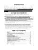
INTRODUCTION The Yetter 2940-106 Hydraulic Air Compressor converts hydraulic power into compressed air. Yetter Hydraulic Compressor units are durably constructed and designed for easy integration to operate the Yetter 2940 Air Adjust System. IF USING THIS COMPRESSOR TO SUPPLY AIR TO OPERATE ANOTHER SYSTEM, INSTALL A REGULATOR PRIOR TO AIR ENTERING THAT SYSTEM WITH PROPER REGULATED AIR SETTINGS RECOMMENDED BY OEM PRODUCT.
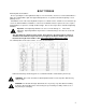
BOLT TORQUE Mounting bolts and hardware Before operating the Yetter Hydraulic Compressor for the first time, check to be sure that all hardware is tight. Check all hardware again after approximately 50 hours of operation and at the beginning of each planting season. All hardware used on the Yetter Hydraulic Compressor is Grade 5 unless otherwise noted. Grade 5 cap screws are marked with three radial lines on the head.
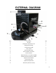
EXTERNAL DIAGRAM Item Description QTY A Air Filter 1 B Compressor Pressure Air Line 1 C Output Elbow Fitting 1 D Tank Pressure Gauge 1 E Tank, 12 GAL 1 F Pressure Relief Valve 1 G Pressure Switch Connector 1 H Pressure Switch 1 I Hydraulic Return to Tank Port -8 ORFS 1 J Hydraulic Pressure Inlet Port -6 ORFS 1 K Hydraulic Control Block 1 L Flow Control Valve 1 M Hydraulic On/Off valve 1 N Tank Drain (valve not shown) 1 6
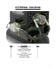
EXTERNAL DIAGRAM Item A B C D E F G H Description Hydraulic On/Off Valve Check Valve Hydraulic Control Block Return to Tank Hose Inlet hose Case Drain Port -6 ORFS Hydraulic motor Housing Assembly QTY 1 1 1 1 1 1 1 1 7
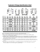
Hydraulic Fittings Identification Chart -Due to common threads, mismatching can happen and could result in leaks and pressure loss -Be sure to verify which style and use dash sizes when ordering replacement parts -NPTF is easily recognizable and looks like regular pipe threads. It is not recommended for hydraulic systems but does exist on some agriculture equipment -SAE ORB is recommended by the NFPA for optimal leakage control in medium and high pressure hydraulic systems.
Quick Start Guide Step 1: Preparing Hydraulic Compressor for Installation After removing the hydraulic compressor from the shipping crate, remove cap from elbow fitting and install air filter assembly securely. Next, remove screen on housing on the side of the sight glass(same side as pressure gauge) and fill compressor pump with oil until oil is in middle of sight glass. See page 16 for further information on filter installment and oil filling.
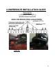
COMPRESSOR INSTALLATION GUIDE Mounting Kits 2940-085 2 Point Hitch Mount Kit 2940-086 Draft Tube or Universal Mount Kit 2940-090 8X12 Bar Hyd. Comp. Mount Kit 2940-091 8X16 Bar Hyd. Comp.
HYDRAULIC CONNECTION GUIDE Hose and Fitting Kits 2940-088 (PLANTER) 2940-089 kit (STAND ALONE) Qty in kit 4 Qty in kit 2 2 3 2 3 2 3 2 1 1 2 1 1 2 1 2 1 2 1 1 2 Part # Part Name Description 2515-324 2515-327 2515-329 2515-411 2515-425 2515-428 2515-430 2515-431 2515-432 2515-433 2515-831 2515-832 2515-833 2515-834 ELBOW ADAPTER ADAPTER ELBOW TEE ELBOW TEE ADAPTER ELBOW ELBOW HOSE HOSE ADAPTER COUPLER 90 DEG, 3/4 SAE TO -6 JIC 3/4-16 SAE TO -6 JIC REDUCER, -8 F TO -6 M JIC 90 DEG 3/4 SAE TO -8JIC
BULKHEAD BLOWER CIRCUIT TEEING BEHIND PIONEER COUPLER SCV DIRECT CASE DRAIN NOTE: THESE ARE EXAMPLES ONLY.
COMMUNICATION HARNESS INSTALLATION WHEN ROUTING HARNESSING, BE SURE TO KEEP CLEAR OF PINCH POINTS, ROTATING PARTS, ETC.
PLUMBING AIR LINE GUIDE BE SURE TO ROUTE ALL AIR TUBING SAFELY STAYING CLEAR OF ALL ROTATING PARTS, PINCH PINCH, ETC.
HARNESS & PLUMBING DIAGRAM 15
MAINTENANCE CLEANING OR REPLACING THE 2940-106 AIR FILTER Filter cleanliness is critical to maintain the performance and service life of the compressor. Recommendations for cleaning are daily and replace every 200 hours OR at beginning of every planting season.
MAINTENANCE WARNING: Keep extremities out of the compressor housing when compressor is running, has potential to run, or recently shut off as there are rotating and high temperature parts that my cause injury. Always turn tractor off and disconnect power before performing any maintenance. LUBRICATION: The compressor is shipped empty of pump lubrication and needs oil added before operation. Provided is a 1 Liter bottle of grade 111 synthetic. Add oil until oil level is seen half way up on the sight glass.
2940-085 PARTS IDENTIFICATION 18
2940-086 PARTS IDENTIFICATION 19
2940-090 & 2940-091 PARTS IDENTIFICATION 20
PARTS IDENTIFICATION 2940-106 21
PARTS IDENTIFICATION BALLOON DESC 1 CHECK VALVE 2 TANK (12 GALLON) 3 VALVE BLOCK 4 FLOW CONTROL 5 VALVE 6 FRAME 7 PUMP 8 COUPLER 9 MOTOR 10 COVER 11 TANK ELBOW FITTING 12 INLET ELBOW FITTING 13 FAN 14 FILTER 15 FILTER ELBOW 16 BACK GUARD 17 AIR MANIFOLD 18 PRESSURE RELIEF VALVE 19 PRESSURE SWITCH 20 GAUGE 21 AIR ELBOW FITTING 22 TANK HOSE 23 INLET HOSE 24 PRESSURE LINE 25 YETTER DECAL PART REFERENCE ONLY 22
PARTS IDENTIFICATION PART REFERENCE ONLY 23
COMPRESSOR TROUBLESHOOTING PROBLEM CAUSE CORRECTIVE ACTION compressor will not operate/run 1)system is not turned on 2)compressor communication harness not installed 3)hydraulics installed improperly 4)compressor not below 125psi 5)compressor locked up/unlubricated compressor runs nonstop, will not build pressure, or stalls: compressor shuts down with air demand 1)severe air leak 2)insufficient hydraulic pressure or flow 3)hydraulic reservoir low 4)air filter plugged 5)faulty Pressure Switch 6)air man