V.T.T. ™ 2000 SERIES VERTICAL TILLAGE TOOL ™ SET-UP AND PARTS MANUAL YETTER MANUFACTURING CO. FOUNDED 1930 Colchester, IL 62326-0358 Toll free: 800/447-5777 309/776-3222 (Fax) Website: www.yetterco.com E-mail: info@yetterco.
FOREWORD You’ve just joined an exclusive but rapidly growing club. For our part, we want to welcome you to the group and thank you for buying a Yetter product. We hope your new Yetter products will help you achieve both goals-increase your productivity and increase your efficiency so that you may generate more profit. This operator’s manual has been designed into four major sections: Foreword, Safety Precautions, Installation Instructions and Parts Breakdown.
SAFETY PRECAUTIONS You can make your farm a safer place to live and work if you observe the safety precautions given. Study these precautions carefully and insist those working with you and for you follow the precautions. Finally, remember this an accident is usually caused by someone’s carelessness, neglect or oversight. CAUTION Consult your implement and tractor operator’s manual for correct and safe operating practices. Be aware of towed implement width and allow safe clearance.
TABLE OF CONTENTS PAGE FORWARD………………………………………………………….……………2 WARRANTY…………………………………………………………….………..2 SAFETY INFORMATION……….………………………………………..……..3 TABLE OF CONTENTS……..….………………………………………..……..4 GENERAL INFORMATION……………………………………………………..5 TORQUE RECOMMENDATIONS…………...…………………………..……..5 ASSEMBLY INSTRUCTIONS….…………………………………………...6-27 OPERATION…………………………………………………………………28-32 MAINTENANCE ………………………………………………………………...33 PARTS IDENTIFICATION………………………………………………….34-54 TROUBLESHOOTING………………………………………………………….
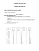
ASSEMBLY INSTRUCTIONS GENERAL INFORMATION Examine all equipment carefully for damage or shortages. Lubricate all bearings and moving parts as assembled. Reference to front, rear, left and right in this installation instruction are made when setting in the operator’s seat facing direction of forward travel. BOLT TORQUE READ THESE INSTRUCTIONS FIRST: 1. Improperly tightened bolts will result in damage, breakage, expense, and down time. 2. Always replace bolts with the specified grade and type. 3.
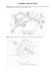
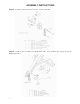
ASSEMBLY INSTRUCTIONS Step 1. Attach axle assembly to the Bridge Hitch Frame. Bolt torque 305 ft/lbs. Attach SMV bracket (not used with optional tank weight kit) to the axle/clamp assembly Step 2. Attach the Wheel/Tire assembly to the axle. Torque the wheel nuts to 100 ft/lbs.
ASSEMBLY INSTRUCTIONS Step 3. Level the Bridge Hitch frame. Install the hitch. Torque bolts to 670 ft/lbs.
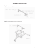
ASSEMBLY INSTRUCTIONS Step 4. Install the safety chain and hose holder. Torque to 300 ft/lbs. Step 5. Install the jack assembly to the Bridge Hitch frame. Next, install the jack storage strap to the Bridge Hitch frame.
ASSEMBLY INSTRUCTIONS Step 6. Assemble the depth adjustment hardware. Step 7. Install the depth adjustment bar to the Bridge Hitch.
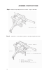
ASSEMBLY INSTRUCTIONS Step 8. Clamp the depth adjustment to the toolbar. Torque to 300 ft/lbs. Step 9. 10 Attach the 4” X 12” hydraulic cylinders to the depth adjustment brackets.
ASSEMBLY INSTRUCTIONS Step 10. Install cylinder stops: 4 X 12 cylinder, toolbar lift. IMPORTANT: Install 5” of 2000-507 cylinder stop kit for 1-1/2” rod.
ASSEMBLY INSTRUCTIONS Step 11. 12 Attach the parallel arms to the Bridge Hitch.
ASSEMBLY INSTRUCTIONS Step 12. Unfold the toolbar from the freight position. Attach the center bracket to the toolbar.
ASSEMBLY INSTRUCTIONS Step 13. 14 Attach the toolbar to the Bridge Hitch.
ASSEMBLY INSTRUCTIONS Step 14. Attach the hydraulic cylinder to the toolbar assembly.
ASSEMBLY INSTRUCTIONS Step 15. 16 Install cylinder stops, 2000-511 (2” cylinder rod) to limit the toolbar wing folding.
ASSEMBLY INSTRUCTIONS Step 16. 2000-509 Cylinder Stop; Cut off length to 13”. Step 17. Install the cylinder stops on the wing fold cylinders.
ASSEMBLY INSTRUCTIONS Step 18. Install the wing fold stops to the toolbar. Do not fully tighten, will need to be adjusted later. Hydraulic Hook Up DANGER: Inspect and replace worn or frayed hydraulic hose. Keep all connections tight, escaping hydraulic fluid under pressure can have sufficient force to penetrate the skin and cause serious personal injury. Fluid escaping from a small hole can be almost invisible. Use a piece of cardboard or wood rather than hands to search for suspected leaks.
ASSEMBLY INSTRUCTIONS Step 19. Install the hydraulic hoses, fitting, and valves.
ASSEMBLY INSTRUCTIONS Step 20. 20 Attach the valve bracket to the Bridge Hitch. Attach the valve to the bracket.
ASSEMBLY INSTRUCTIONS Step 21. Measure the toolbar to find the centerline. Mark the toolbar for clamp plate locations as shown in the example diagram L584-2990-156-002. Note: It is very important that the clamp plates are tightened square to the toolbar. Attach the clamp kits to the toolbar.
ASSEMBLY INSTRUCTIONS Step 22. Install the roll pin to the shank. Insert the locking collar into the coulter swivel casting. From the bottom, fit the shank into the coulter swivel/collar assembly. Allow the coulter to swivel, turn the shank so that the roll pin does not engage the notch in the casting. Install and tighten the set screw into the locking collar, torque 100 ft/lb. maximum. Step 23. Install the shank coulter assembly to the clamp kit, secure with the cotter pin and set screws.
ASSEMBLY INSTRUCTIONS Step 24. Attach the blades and hub cap straps to the coulter assembly using the carriage bolts, lock washers and nuts. Fully tighten, torque 80-85 ft./lb.
ASSEMBLY INSTRUCTIONS Step 25. Attach the tank cradle to the mount brackets using the 5/8” X 4” bolts and lock nuts. Step 26. Attach the tank cradle assembly to the frame/axle using the existing ¾” bolts. The upper clamp plate will not be re-used.
ASSEMBLY INSTRUCTIONS Step 27. Install the plug fittings into the tank – use thread tape or thread compound. Attach the SMV decal to the tank.
ASSEMBLY INSTRUCTIONS Step 28. Set the tank into the cradle and secure with the straps.
ASSEMBLY INSTRUCTIONS Step 29. Attach the 2000-290 weight bracket to the toolbar using the (8) ¾ “ X 10” bolts, (4) mount plates and (8) ¾” locknuts. Add (9) JD suitcase weights to the weight bracket and secure with (2) ¾” bolts and locknuts.
OPERATION WARNING: Do not allow children to operate this equipment. Do not allow riders on the tractor or implement. Failure to heed may result in personal injury or death. 1 IMPORTANT: Do not operate the coulter depth so deep that the coulter hubs are in the soil, this will cause premature bearing failure. Yetter Model 2000 Series Vertical Tillage Tool¥ coulters are designed for tillage 3” to 5” deep and to be operated 6-10 mph. • During assembly, the coulters should be set up to swivel.
OPERATION Hydraulic Hook Up DANGER: Inspect and replace worn or frayed hydraulic hose. Keep all connections tight, escaping hydraulic fluid under pressure can have sufficient force to penetrate the skin and cause serious personal injury. Fluid escaping from a small hole can be almost invisible. Use a piece of cardboard or wood rather than hands to search for suspected leaks. Failure to heed may result in personal injury or death.
OPERATION PREPARING V.T.T. TM FOR TRANSPORT STEP 1. STEP 2. STEP 3. STEP 4. STEP 5. 30 Remove wing flex cylinder stops from the 5 X 16 hydraulic fold cylinders, place in storage location. Fully raise toolbar against 4 X 12 hydraulic lift cylinder stops.
OPERATION PREPARING V.T.T. FOR FIELD STEP 1. STEP 2. STEP 3. STEP 4. STEP 5.
OPERATION COULTER BLADE DEPTH ADJUSTMENT To change to the operating depth of the coulter blades, the adjustment is to be pinned in one of seven th holes. The top hole is for deep tillage and the bottom hole is for shallow tillage. Initially, use the 4 hole, then adjust the bracket according to field conditions. Liquid ballast weight can be added with the use of the 2000-037 tank kit.
MAINTENANCE 1 WARNING: Never clean, lubricate or adjust a machine that is in motion. Failure to heed may result in serious personal injury or death. COULTER BLADE WEAR Blade wear can affect performance in loose trash conditions. Depth control and plugging problems can result. It may be necessary to replace blades. 1 WARNING: If required to service unit in raised position, be sure to close the hydraulic valves. Failure to heed may result in serious personal injury or death.
PARTS INDENTIFICATION 34
PARTS INDENTIFICATION 35
PARTS INDENTIFICATION 36
PARTS INDENTIFICATION 37
PARTS INDENTIFICATION 38
PARTS INDENTIFICATION 39
PARTS INDENTIFICATION 40
PARTS INDENTIFICATION 41
PARTS INDENTIFICATION 42
PARTS INDENTIFICATION 43
PARTS INDENTIFICATION 44
PARTS INDENTIFICATION 45
PARTS INDENTIFICATION 46
PARTS INDENTIFICATION 47
PARTS INDENTIFICATION 48
PARTS INDENTIFICATION 49
PARTS INDENTIFICATION 50
PARTS INDENTIFICATION 51
PARTS INDENTIFICATION 52
PARTS INDENTIFICATION 53
PARTS INDENTIFICATION 54
TROUBLESHOOTING Problem Cause Solution Setting coulter depth equally Frame not set correctly Ensure that in operation the frame is level. Blade not penetrating Insufficient coulter spring pressure. Tighten coulter spring locknut down 1” further. Coulter incorrectly installed Adjust height of coulter by sliding shank down at the clamp kit. Spring not deflecting Excessive spring pressure Back off coulter spring locknut.
Our name Is getting known Just a few years ago, Yetter products were sold primarily to the Midwest only. Then we embarked on a program of expansion and moved into the East, the South, the West and now north into Canada. We’re even getting orders from as far away as Australia and Africa. So, when you buy Yetter products . . .you’re buying a name that’s recognized. A name that’s known and respected.