
User Manual

M
~
=
A
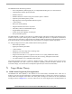
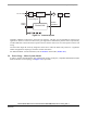
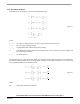
C Line Voltage
Power Stage
Control Unit
Position
Sensors
LOAD
Speed
Setting
Position
Feedback
Control Signals
Power Stage - Motor System Model
3-Phase BLDC Motor Control with Sensorless Back-EMF, ADC, Zero Crossing, Rev. 3
Freescale Semiconductor 7
Preliminary
Figure 3-4. Classical System
Therefore, additional connections to the motor are necessary. This may not be acceptable for some kind of
applications. There are at least two reasons why you might want to eliminate the position sensors: impossibility
to make additional connections between position sensors and the control unit cost of the position sensors and
wiring.
The first reason might be solved by integration of the driver within the motor body. However, a significant
number of applications requiring a sensorless solution still remain.
For additional BLDC control information, refer to Section 5. and AN1627 (Section 11.2).
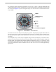
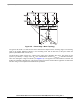
3.4 Power Stage - Motor System Model
In order to explain and simulate the idea of Back-EMF sensing techniques, a simplified mathematical model
based on the basic circuit topology (see
Figure 3-5), is provided.