
User Manual


Commutation Control Settings
3-Phase BLDC Motor Control with Sensorless Back-EMF, ADC, Zero Crossing, Rev. 3
Freescale Semiconductor 53
Preliminary
10.2 Commutation Control Settings
In order to get the motor reliably started, the commutation control constants must be properly set.
10.2.1 Alignment Period
The time duration of the Alignment state must be long enough to stabilize the motor, before it starts.
This duration is set in seconds in bldcadczcdefines.h.
#define x_PER_ALIGNMENT_S 0.5 /* Alignment period [s] */
Notes: For the first tuning, it is recommended to set this duration long enough (for example, 5 seconds). Then,
if the motor works well, it can be significantly shortened (for example, 0.1 seconds).
10.2.2 Start-up Periods
The constants defining the start up need to be changed according to the drive dynamic.
All settings in this section are in bldcadczcdefines.h:
#define x_PER_CMTSTART_US 7200.0 /* Start Commutation Period [micros] */
#define x_PER_TOFFSTART_US 14400.0 /* Start Zero Crossing
Toff Period [micros] */
x_PER_CMTSTART_US is the commutation period used to compute the first (start) commutation period.
x_PER_TOFFSTART_US is the first (start) Toff interval after commutation (where Back-EMF Zero Crossing is
not sensed).
The unit of this constant is 1 µs.
Notes: It is recommended to set x_PER_TOFFSTART_US = 2*x_PER_CMTSTART_US.
Next, set the first motor commutation period = x_PER_CMTSTART_US * 2
The Back-EMF Zero Crossing is not sensed during the first duration since it is very short. Hence, the Zero
Crossing information is not reliable during this period.
Notes: Setting these constants is an experimental process. It is difficult to use a precise formula because there
are many factors involved which are difficult to obtain in case of real drive (motor and load
mechanical inertia, motor electromechanical constants, and sometimes also the motor load). Therefore,
constants need to be set for a specific motor.
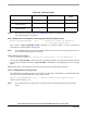
Table 10-2 aids in the setting of constants.