
User Manual


State Diagram
3-Phase BLDC Motor Control with Sensorless Back-EMF, ADC, Zero Crossing, Rev. 3
Freescale Semiconductor 51
Preliminary
9. DSC Usage
Figure 9-1 shows how much memory is needed to run the BLDC motor drive with Back-EMF Zero Crossing
using ADC in a speed-closed loop. A part of the device’s memory is still available for other tasks.
Table 9-1. RAM and FLASH Memory Usage for SDK2.2
Memory
(in 16 bit Words)
Available
56F803
56F805
Used
Application + Stack
Used
Application without PC master
software
, SCI
Program FLASH 31.5K 14288 10568
Data RAM 2K 1481+352 1145+352
10. Setting of Software Parameters for Other Motors
The software was tuned for three hardware and motor kits (EVM, LV, HV) as described in Section 6. and
Section 4.1. It can of course be used for other motors, but the software parameters need to be set accordingly.
Most of the parameters are located in the file (External RAM version):
...\dsp5680xevm\nos\applications\bldc_adc_zerocross\bldcadczcdefines.h
and config files:
...\dsp5680xevm\nos\applications\bldc_adc_zerocross\configextram\appconfig.h
or in the file (Flash version):
...\dsp5680xevm\nos\applications\bldc_adc_zerocross\configFlash\appconfig.h
The motor control drive usually needs setting/tuning of the following:
• Dynamic parameters
• Current/voltage parameters
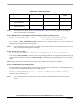
The software selects valid parameters (one of the three parameter sets) based in the identified hardware. The
table below shows the starting string of the software constants used for each hardware set.
Table 10-1. Software Parameters Marking
Hardware Set Software Parameters Marking
Low Voltage Evaluation Motor Hardware Set EVM_yyy
Low Voltage hardware set LV_yyy
High Voltage Hardware Set HV_yyy
In the following text the EVM, LV, HV are replaced with x. The sections are sorted in recommended order
(when one is tuning/changing parameters).
Notes: The most important constants for reliable motor start-up are described in Section 10.2.2 and in
Section 10.1.2.