
User Manual

electric
al
angle
BLDC MotorTargeted by This Application
3-Phase BLDC Motor Control with Sensorless Back-EMF, ADC, Zero Crossing, Rev. 3
Freescale Semiconductor 5
Preliminary
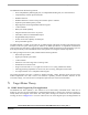
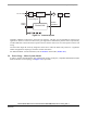
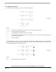
Figure 3-2. Three Phase Voltage System
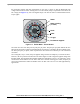
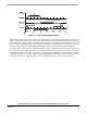
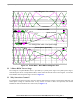
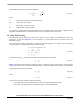
Figure 3-3 shows the number of waveforms, the magnetic flux linkage, the phase Back-EMF voltage and the
phase-to-phase Back-EMF voltage. The magnetic flux linkage was measured by calculating the integration
phase Back-EMF voltage, which was measured on the non-fed motor terminals of the BLDC motor. As can be
seen, the shape of the Back-EMF is approximately trapezoidal and the amplitude is a function of the actual
speed. During the speed reversal the amplitudeis changed and its sign and the phase sequence change too.
The filled areas in the tops of the phase Back-EMF voltage waveforms indicate the intervals where the
particular phase power stage commutations are conducted. As can be seen, the power switches are cyclically
commutated through the six steps. The crossing points of the phase Back-EMF voltages represent the natural
commutation points. At the normal operation, the commutation is performed here. Some control techniques
lead the commutation by a defined angle in order to control the drive above the PWM voltage control.