
User Manual

State Diagram
3-Phase BLDC Motor Control with Sensorless Back-EMF, ADC, Zero Crossing, Rev. 3
Freescale Semiconductor 49
Preliminary
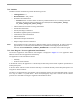
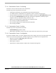
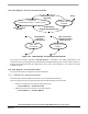
7.3.8 State Diagram - Process Current PI Controller
Commutation Status
U_Desired =
PI (Reference Current - Actual Current)
Start ADC
Conversions
Commutation
Current Control
Disabled
Set Current Control
Request
Alignment
Stopped/Starting/Running
ADC Conversion
Complete Interrupt
(PWM period)
PWM Reload
Interrupt
(PWM period)
Current Control
Request
Reset
Figure 7-13. State Diagram - Process Speed PI Controller
The Current PI controller algorithm, controllerPItype1, is described in the SDK documentation. The
controller execution (sampling) period is determined by the PWM module period, since the ADC conversion is
started each PWM reload (once per PWM period). The Current Control Request is set in ADC Conversion
Complete Interrupt.
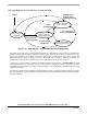
7.3.9 State Diagram - Process Fault Control
The process Fault State is described in Interrupt subroutines.
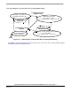
7.3.9.1 PWM Fault A Interrupt Subroutine
This subroutine is called at PWM A (or PWM in case of 56F803) Fault Interrupt.
In this interrupt subroutine, the following faults from the PWM Fault pins are processed:
• When Overvoltage occurs (the Overvoltage fault pin set)
— DriveFaultStatus |= OVERVOLTAGE
• When Overcurrent occurs (the Overcurrent fault pin set)
— DriveFaultStatus |= OVERCURRENT