
User Manual

State Diagram
3-Phase BLDC Motor Control with Sensorless Back-EMF, ADC, Zero Crossing, Rev. 3
Freescale Semiconductor 47
Preliminary
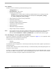
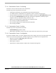
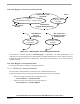
7.3.6 State Diagram - Process ADC Zero Crossing Offset Setting
measure U_Dc_Bus and
free phase average U_Phx
Commutation status:
Alignment
calibration coefficient
Coef_Calibr_U_Phx =
setting of ADC Offset registers to
= (U_Dc_Bus_Half + U_Phx)/U_Dc_Bus
U_Dc_Bus_Half =
Coef_Calibr_U_Phx * U_Dc_Bus
Commutation status:
Alignment End
Commutation status:
Running/Starting
Commutation status:
Stopped
Zero Crossing Offset
Setting Disabled
Reset
Figure 7-11. State Diagram - Process ADC Zero Crossing Offset Setting
The Figure 7-11 state diagram describes the tuning process of the ADC (Zero Crossing) Offset Registers
described in Section 5. and Section 7.2.4.