
User Manual
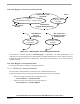

State Diagram
3-Phase BLDC Motor Control with Sensorless Back-EMF, ADC, Zero Crossing, Rev. 3
Freescale Semiconductor 45
Preliminary
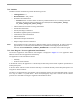
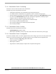
7.3.4.4 Commutation Control - Set Starting
This state is used to set the start of the motor commutation.
The following actions are performed in this state:
• Commutation initialized to start commutation step and required direction
• Two additional motor commutations are prepared (in order to create the starting torque)
• setting commutation parameters and commutation handler initialization by bldczcHndlrInit algorithm
• first action from bldczcHndlrInit algorithm (for commutations algorithms) is timed by Output
Compare Timer for Commutation timing control (OC Cmt)
• PWM is set according the above prepared motor commutation steps
• Zero Crossing is initialized by bldcZCrosInit
• Zero Crossing computation is initialized by bldczcComputInit
• Zero Crossing is Enabled
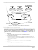
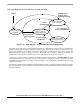
7.3.4.5 Commutation Control - Set Stop
The following actions are performed in this state:
• bldczcHndlrStop algorithm is called
• PWM output is disabled in order to stop motor rotation and switch off the motor power supply.
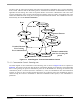
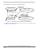
7.3.4.6 Commutation Control - SetAlignment
In this state, the BLDC motor is set to the Alignment state, where voltage is put across two motor phases and a
current is set to be at the required value. The following actions are provided in the Set Alignment state:
• PWM set according to Align_Step_Cmt variable status
• Current controller is initialized
• PWM output is enabled
• Aligned Time is timed by Output Compare Timer for Speed and Alignment