
User Manual
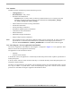
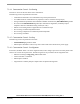
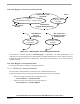

Drive Fault
BLDC Run
Drive Fault
BLDC Stop
with Required Speed
(Switch = Stop) || (abs (Required Speed) <= Minimal Speed)
(Switch = Run) & (abs (Required Speed) > Minimal Speed)
Up Button
Increment
Required Speed
Down Button
Decrement
Required Speed
Drive Fault
Reset
PC Master Software
Set
Required Speed
Required Speed setting
Emergency Stop
Software Design
3-Phase BLDC Motor Control with Sensorless Back-EMF, ADC, Zero Crossing, Rev. 3
42 Freescale Semiconductor
Preliminary
Figure 7-7. State Diagram - Process Application State Machine
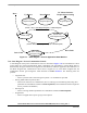
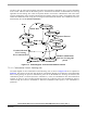
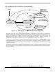
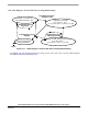
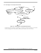
7.3.4 State Diagram - Process Commutation Control
A State Diagram of the process Commutation Control is illustrated in Figure 7-8. The Commutation Control
process takes care of the sensorless BLDC motor commutation. The requirement to run the BLDC motor is
determined by the upper software level Application State Machine. When the Application State Machine is in
the BLDC Stopped state, Commutation Control status is stopped. If it is in the BLDC Stopped state, the
Commutation Control goes through the states described in Section
Section 5.. The following states are
possible:
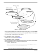
• Alignment state
— Motor is powered with current through two phases - no commutations provided
• Starting (Back-EMF Acquisition) state
— Motor starts with first two commutations, then it is running (as in the Running state) using Start
parameters for commutation calculation StartComputInit (so the commutation advance angle and
the Per_Toff time are different)
• Running state
— Motor is running with Run parameters for commutation calculation RunComputInit
• Stopped state
— Motor is stopped with no power going to motor phases