
User Manual

State Diagram
3-Phase BLDC Motor Control with Sensorless Back-EMF, ADC, Zero Crossing, Rev. 3
Freescale Semiconductor 41
Preliminary
7.3.2 Initialize
The Main software initialization provides the following actions:
• CmdApplication = 0
• DriveFaultStatus = NO_FAULT
• PCB Motor Set Identification
— boardId function is used to detect one of three possible hardware sets. According to the used
hardware, one of three control constant sets are loaded (functions EVM_Motor_Settings,
LV_Motor_Settings, HV_Motor_Settings)
• ADC Initialization with Zero Crossing initialization
• LED diodes initialization
• Switch (Start/Stop) initialization
• Push Buttons (Speed up/down) initialization
• Commutation control initialization
• PWM initialization
• PWM fault interrupts initialization
• Output Compare Timers initialization
Notes: The EVM board can be connected to a different number of power stage boards. In order to assure the
right hardware is connected, board identification is performed. When inappropriate hardware is
detected, the DriveFaultStatus|=WRONG_HARDWARE is set and the motor remains stopped.
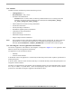
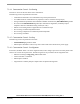
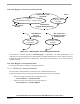
7.3.3 State Diagram - Process Application State Machine
The Process Application State Machine state diagram is displayed in Figure 7-7. The Application State
Machine controls the main application functionality.
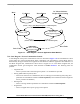
The application can be controlled as follows:
• Manually
• From PC master software
In the manual control, the application is controlled by the Start/Stop switch and the Up/Down push buttons to
set Required Speed.
In the PC master software control mode the Start/Stop is controlled manually and the Required Speed is set
using the PC master software.
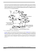
The motor is stopped whenever the absolute value of Required speed is lower then Minimal Speed or switch
set to stop or if there is a system failure - Drive Fault (Emergency Stop) state is entered. All the software
processes are controlled according this Application State Machine status.