
User Manual

Software Design
3-Phase BLDC Motor Control with Sensorless Back-EMF, ADC, Zero Crossing, Rev. 3
40 Freescale Semiconductor
Preliminary
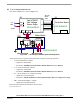
7.2.6 Process Current PI Controller
The process is similar to the Speed controller. The I_Dc_Bus current is controlled based on the
U_Dc_Bus_Desired Reference current. The current controller is processed only during the Alignment state.
The current controller works with a constant execution (sampling) period which is determined by the following
PWM frequency:
Current Controller period = 1/pwm frequency.
The PI controller proportional and integral constants were set experimentally.
7.2.7 Process PWM Generation
The Process PWM Generation creates the following:
• BLDC motor commutation pattern as described in Section 1.
• Required duty cycle
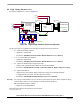
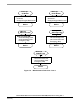
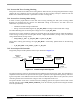
7.2.8 Process Fault Control
The Process Fault Control is used for drive protection (see Figure 7-5). The DriveFaultStatus is passed to the
PWM Generation process and to the Application State Machine process in order to disable the PWMs and to
control the application accordingly.
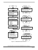
7.3 State Diagram
All the software state diagrams are described below.
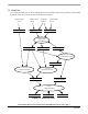
7.3.1 Main Software States - General Overview
The software can be split into the following processes:
• Process Application State Machine
• Process Commutation Control
• Process ADC Zero Crossing Checking
• Process Zero Crossing Offset Setting
• Process Speed PI Controller
• Process Current PI Controller
• Process PWM Generation
• Process Fault Control
For detailed information, refer to Section 7.2. The general overview of the software states is in the State
Diagram - Process Application State Machine; which is the highest level. (Only the process Fault Control is on
the same level because of the motor emergency stop.)
The status of all the processes after reset is defined in Section 7.3.2.