
User Manual

Data Flow
3-Phase BLDC Motor Control with Sensorless Back-EMF, ADC, Zero Crossing, Rev. 3
Freescale Semiconductor 39
Preliminary
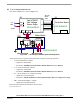
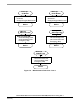
7.2.3 Process ADC Zero Crossing Checking
This process is based on the ADC Zero Crossing feature. When the free (not energized) phase branch voltage
changes the sign comparing previous conversion results, the Zero Crossing interrupt is initiated. Then the
BLDC motor commutation control is performed in the Zero Crossing ISR.
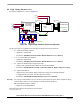
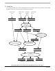
7.2.4 Process Zero Crossing Offset Setting
In order to assure proper behavior of the ADC Zero Crossing Checking, the ADC (Zero Crossing) Offset
Registers are initialized the way that the zero Back-EMF voltage is converted to zero ADC value. The
initialization is provided in two steps:
• Calibration of Phase Voltage Coefficients
• Setting of the ADC Offset Registers (U_Dc_Bus_Half) according to measured DC-Bus voltage
The ADC Offset Registers for all free phase voltages are set to U_Dc_Bus_Half.
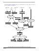
The phase Zero Crossing calibration coefficient is obtained during the Alignment state (to reflect the unbalance
of the sensing circuitry) from non-fed phase branch voltage measurements (average value) and DC-Bus
voltage measurements (average value).
• Coef_Calibr_U_Phx = (U_Dc_Bus_Half + U_Phx)/U_Dc_Bus
During motor running (and starting) the U_Dc_Bus_Half is continuously updated based on the following
formula:
• U_Dc_Bus_Half = Coef_Calibr_U_Phx * U_Dc_Bus
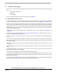
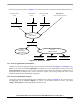
7.2.5 Process Speed PI Controller
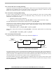
The general principle of the speed PI control loop is illustrated in Figure 7-6.
PI
Controller
Controlled
System
Speed
Error
Reference
Speed
Corrected
Speed
(U_Desired)
(Omega_Desired)
Actual Motor
Speed
(Omega_Actual)
-
Figure 7-6. Closed Loop Control System
The speed closed loop control is characterized by the feedback of the actual motor speed. This information is
compared with the reference set point and the error signal is generated. The magnitude and polarity of the error
signal corresponds to the difference between the actual and desired speed. Based on the speed error, the PI
controller generates the corrected motor voltage in order to compensate for the error.
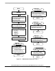
The speed controller works with a constant execution (sampling) period. The request is driven from a timer
interrupt with the constant PER_SPEED_SAMPLE_S. The PI controller proportional and integral constants
were set experimentally.