
User Manual

Software Design
3-Phase BLDC Motor Control with Sensorless Back-EMF, ADC, Zero Crossing, Rev. 3
38 Freescale Semiconductor
Preliminary
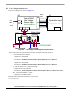
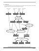
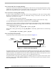
Protection processes are shown in Figure 7-5. It consists of processes described in the following sub-sections.
U_Dc_Bus
Process
Fault Control
DriveFaultStatus
Temperature
PWM Faults
(OverVoltage/OverCurrent)
DC-Bus Voltage
(A/D)
Temperature
(A/D)
DC-Bus Current
(A/D)
I_Dc_Bus
PVAL0,PVAL1 PVAL4,PVAL5PVAL2,PVAL3
Process
PWM Generation
Process
Application
State Machine
Figure 7-5. Data Flow - Part 3
7.2.1 Process Application State Machine
This process controls the application subprocesses by status and command words (Figure 7-3 and Figure 7-4).
Based on the status of the Cmd_Application Cmd flags (set by the Commutation Control process) the
Cmd_Application Rq flags are set to request calculation of the Current PI Controller (Alignment state) or
Speed PI Controller (Running state) and to control the angular speed setting (reflects the status of the
START/STOP Switch and the Run/Stop commands).
7.2.2 Process Commutation Control
This process controls sensorless BLDC motor commutations as explained in Section 5.. The process outputs,
the Step_Cmt and the Cmt_Drv_RqFlag, are used to set the PWM Generation process. The output
Omega_Actual_Mech is used for the Speed Controller process.