
User Manual

Data Flow
3-Phase BLDC Motor Control with Sensorless Back-EMF, ADC, Zero Crossing, Rev. 3
Freescale Semiconductor 37
Preliminary
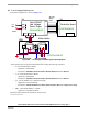
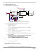
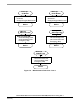
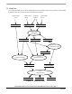
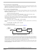
The control algorithm of the BLDC motor drive with Back-EMF Zero Crossing using AD converter, is
described in
Figure 7-3 and Figure 7-4.
Phase
U_ZC3Phase
Voltages
Omega_Required_Mech
PVAL0,PVAL1 PVAL4,PVAL5PVAL2,PVAL3
Process
Process
PWM Generation
Manual Speed PC
Setting
Master
Process
Commutation Control
ApplicationMode
START/STOP
Switch
Step_Cmt,
Cmt_Drv_RqFlag
Status_Commutation Cmd_Application
U_Dc_Bus
DC-Bus Voltage
(A/D)
Process
Zero Crossing Offset
U_Dc_Half
Process
ADC Zero Crossing
ZCross Interrupt Flag
Cmd_Application
Setting
Checking
Application
State Machine
Figure 7-4. Data Flow - Part 2