
User Manual

Software Design
3-Phase BLDC Motor Control with Sensorless Back-EMF, ADC, Zero Crossing, Rev. 3
36 Freescale Semiconductor
Preliminary
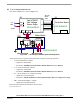
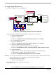
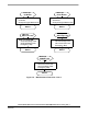
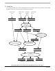
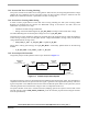
7.2 Data Flow
The control algorithm process values obtained from the user interface and sensors, generates 3-phase PWM
signals for motor control (as can be seen on the data flow analysis).
Omega_Required_Mech
PVAL0,PVAL1 PVAL4,PVAL5PVAL2,PVAL3
Omega_Desired_Mech
Omega_Actual_Mech
Process
Process
PWM Generation
U_Desired
Manual Speed PC Master
Setting
Process
Commutation Control
Speed PI Controller
Process
Current PI Controller
Status_Commutation
Cmd_Application
DC-Bus Current
(A/D)
I_Dc_Bus
ApplicationMode
START/STOP
Switch
Step_Cmt,
Cmt_Drv_RqFlag
Process
Application
State Machine
Software
Figure 7-3. Data Flow - Part 1