
User Manual

Main Software Flow Chart
3-Phase BLDC Motor Control with Sensorless Back-EMF, ADC, Zero Crossing, Rev. 3
Freescale Semiconductor 33
Preliminary
7. Software Design
This section describes the design of the software blocks of the drive. The software is described in the following
terms:
• Main Software Flow chart
• Data Flow
• State Diagram
For more information of the used control technique refer to Section 5.
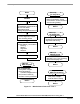
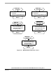
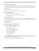
7.1 Main Software Flow Chart
The main software flow chart incorporates the Main routine entered from Reset and interrupt states. The Main
routine includes the initialization of the device and the main loop. (It is shown in
Figure 7-1, and Figure 7-2.)
The main loop incorporates Application State Machine - the highest software level which proceeds settings for
other software levels (BLDC motor Commutation Control, Zero Crossing Offset Control, Speed Control,
Alignment Current Control). The inputs of Application State Machine is Run/Stop Switch state and Required
Speed Omega and Drive Fault Status. Required Mechanical Speed can be set from the PC master software or
manually by Up/Down buttons.
Commutation Control proceeds BLDC motor commutation with the states described in Section 5. and
Section 7.3.4.
The Speed Control detailed description is in Section 7.2.5 and Section 7.3.7. Alignment Current Control is
described in Section 7.2.6 and Section 7.3.8.
The Run/Stop switch is checked to provide an input for Application State Machine (ApplicationMode Start or
Stop).
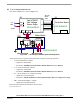
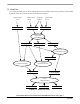
The interrupt subroutines provide commutation Timer services, ADC starting in the PWM reload interrupt,
ADC service, ADC Zero Crossing checking, Limit analog values handling, and overcurrent and overvoltage
PWM fault handling.
The Commutation Timer ISR is used for Commutation Timing and Commutation Control and Zero Crossing
Checking.
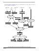
The Speed/Alignment Timer ISR is used for Speed regulator time base and for Alignment state duration
timing.
The PWM Reload ISR is used to start ADC conversion for ADC Zero Crossing and other channels and
memorize the sampling time T_ZCSample.
The ADC Zero Crossing ISR is used to evaluate Back-EMF Zero Crossing.
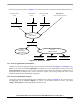
The ADC completion ISR is used to read voltages, current and temperature samples from the ADC converter.
It also sets Current control and Zero Crossing Offset Request flags when the Current Control or Zero Crossing
Offset setting are enabled.
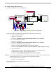
The other interrupts (Figure 7-2) are used for System Fault handling and setting of Required Mechanical
Speed input for Application State Machine (ApplicationMode Start or Stop).