
User Manual

Low Voltage hardware set
3-Phase BLDC Motor Control with Sensorless Back-EMF, ADC, Zero Crossing, Rev. 3
Freescale Semiconductor 31
Preliminary
6.3 Low Voltage hardware set
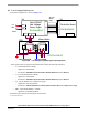
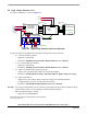
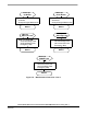
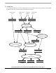
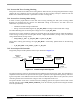
The system configuration is shown in Figure 6-2.
MB1
J5
Controller Board
Black
White
ECMTRLOVBLDC
SG40N
ECLOVACBLDC
Motor-Brake
White
Red
U2
12VDC
+12
Not Connec ted
U1
J30
(P1)
3ph AC/BLDC
Low Voltage
Power Stage
Red
J13
SM40N
J20
Bl ack
Not Connected
J19
GND
40w
flat
ribbon
cable
DSP5680xEVM
J16 J17 J18
Figure 6-2. Low Voltage Hardware System Configuration
All the system parts are supplied and documented according the following references:
• U1 Controller Board for 56F805:
— supplied as: 56F805EVM
— described in: 56F805EVMUM Evaluation Module Hardware User’s Manual
• or U1 Controller Board for 56F803:
— supplied as: 56F803EVM
— described in: 56F803EVMUM Evaluation Module Hardware User’s Manual
• U2 - 3 ph AC/BLDC Low Voltage Power Stage
— supplied as: ECLOVACBLDC
— described in: MEMC3PBLDCLVUM/D 3-phase Brushless DC Low Voltage Power Stage
• MB1 - Motor-Brake SM40N + SG40N
— supplied as: ECMTRLOVBLDC
Information about boards and documents can be found T:
www.freescale.com