
User Manual

BLDC MotorTargeted by This Application
3-Phase BLDC Motor Control with Sensorless Back-EMF, ADC, Zero Crossing, Rev. 3
Freescale Semiconductor 3
Preliminary
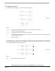
The PWM block has the following features:
• Three complementary PWM signal pairs, six independent PWM signals, or a mixture thereof
• Complementary channel operation features
• Deadtime insertion
• Deadtime distortion correction using current status inputs or software
• Separate top and bottom polarity control
• Edge-aligned or center-aligned PWM reference signals
• 15-bit resolution
• Half-cycle reload capability
• Integral reload rates from one to 16 period
• Individual, software-controlled PWM output
• Programmable fault protection
• 20-mA current sink capability on PWM pins
• Write-protectable registers
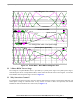
The PWM module is capable of providing the six PWM signals with bipolar switching (the diagonal power
switches are driven by the same signal). In addition, the PWM provides the six-step BLDC commutation
control (where one motor phase is left unpowered so the Back-EMF can be detected). The PWM duty cycle can
be set asynchronously to the commutation of the motor phases event using the channel swap feature.
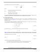
An Analog-to-Digital Converter (ADC) module has the following features:
• Dual ADCs per module
• Eight input channels per module
• 12-bit resolution
• Monotonic over entire range with no missing codes
• Simultaneous conversion mode
• Single conversion time in 1.7 us; eight conversions in 5.3 us (using simultaneous mode)
• Interrupt generating capabilities at: end-of-scan, Zero Crossing, and high/low limit check
• Two output formats: two’s compliment and unsigned
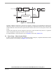
The Analog-to-Digital Converter is utilized to measure DC-Bus voltage, DC-Bus current and the power
module temperature. The ADC’s Hi/Lo level detection capability provides automatic detection of the
over/under-voltage, over-current and over temperature protection (serviced in associated ISR).
3. Target Motor Theory
3.1 BLDC MotorTargeted by This Application
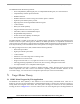
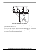
The Brushless DC motor (BLDC) is also referred to as an electronically commuted motor. There are no
brushes on the rotor and the commutation is performed electronically at certain rotor positions. The stator is
usually made from magnetic steel sheets. The stator phase windings are inserted in the slots (distributed
winding) as shown on Figure 3-1 or it can be wound as one coil on the magnetic pole. The magnetization of