
User Manual

Low Voltage Evaluation Motor Hardware Set
3-Phase BLDC Motor Control with Sensorless Back-EMF, ADC, Zero Crossing, Rev. 3
Freescale Semiconductor 29
Preliminary
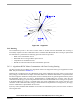
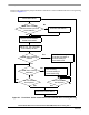
5.5 Speed Control
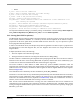
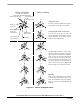
The speed-closed loop control is provided by a PI regulator as described in Section 7.2.5. The actual speed
(Omega_Actual) is computed from the average of two Back-EMF Zero Crossing periods (time intervals)
gained from sensorless commutation control block.
The speed controller works with a constant execution (sampling) period PER_SPEED_SAMPLE_S (request
from timer interrupt).
6. Hardware
6.1 System Outline
The motor control system is designed to drive the 3-phase BLDC motor in a speed-closed loop.
The application can run on Freescale’s motor control devices using the EVM Board:
•56F803
•56F805
•56F807
The hardware setup of the system for a particular device varies only by the EVM Board used. The application
software is identical for all devices, the EVM and chip differences are handled by SDK drivers for the
particular EVM board.
Automatic board identification allows one program to run on each of three hardware and motor platforms
without any parameter change:
• Low Voltage Evaluation Motor Hardware Set
• Low Voltage hardware set
• High Voltage Hardware Set
The hardware setup is shown in Figure 6-1, Figure 6-2 and Figure 6-3. More info can also be found in
Section 11.1.
Notes: The detailed description of individual boards can be found in the User’s Manuals for each board. The
user manual incorporates the schematic of the board, description of individual function blocks and bill
of materials. The individual boards can be ordered from Freescale as a standard product.
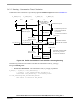
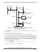
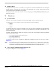
6.2 Low Voltage Evaluation Motor Hardware Set
The system configuration is shown in Figure 6-1.