
User Manual
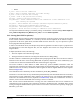

RunningAlign
Back-EMF Zero Crossings
Ideal Commutation Pattern when position is known
Real Commutation Pattern when position is estimated
Phase Back-EMF’s
Phase A
Phase C
Phase B
1’
st
2’
nd
3’
rd
4’
rd
.................
C
TOP
C
BOT
A
TOP
B
TOP
C
TOP
B
TOP
A
BOT
B
BOT
C
BOT
A
BOT
C
TOP
C
BOT
A
TOP
B
TOP
B
TOP
A
BOT
B
BOT
C
BOT
A
BOT
C
TOP
Starting (Back-EMF Acquisition)
Sensorless Commutation Control
3-Phase BLDC Motor Control with Sensorless Back-EMF, ADC, Zero Crossing, Rev. 3
Freescale Semiconductor 27
Preliminary
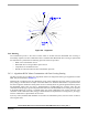
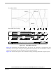
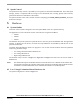
Figure 5-10. Back-EMF at Start-Up
Figure 5-10 demonstrates the Back-EMF during the start-up. The amplitude of the Back-EMF varies
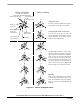
according to the rotor speed. During the Starting (Back-EMF Acquisition) state the commutation is done in
advance. In the Running state the commutation is done at the right moments.
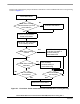
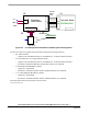
Figure 5-11 illustrates the sequence of the commutations during the Starting (Back-EMF Acquisition) state.