
User Manual
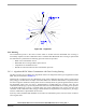
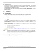

Border of
stator pole
Stator magnetic field
Rotor magnetic
Phase winding
Rotor movement
field
Direction of
Phase current
during one
commutation
(created by PM)
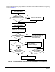
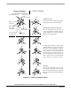
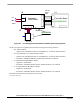
Zero Crossing
edge indicator
Motor is Running
at steady-state condition
Motor is Starting
Alignment State
Starting (Back-EMF Acquisition)
Running
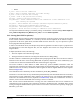
The rotor position is stabilized by applying
PWM signals to only two motor phases
The two fast (faster then the rotor can
move) commutation are applied to create an
angular difference of the stator magnetic
field and rotor magnetic field.
The Back-EMF feedback is tested. When
the Back-EMF Zero Crossing is recognized
the time of new commutation is evaluated.
Until at least two successive Back-EMF
Zero Crossings are received the exact com-
mutation time can not be calculated. There-
fore the commutation is done in advance in
order to assure that successive Back-EMF
Zero Crossing event would not be missed.
After several Back-EMF Zero Crossing
events the exact commutation time is calcu-
lated. The commutation process is adjusted.
Motor is running with regular Back-EMF
feedback.
with regular Back-EMF feedback
Control Technique
3-Phase BLDC Motor Control with Sensorless Back-EMF, ADC, Zero Crossing, Rev. 3
26 Freescale Semiconductor
Preliminary
Figure 5-9. Vectors of Magnetic Fields