
User Manual

Sensorless Commutation Control
3-Phase BLDC Motor Control with Sensorless Back-EMF, ADC, Zero Crossing, Rev. 3
Freescale Semiconductor 25
Preliminary
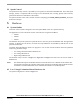
•Where:
T_Cnt0 = time of the last commutation
T_Next = Time of the Next Time event (for Timer Setting)
T_zCros = Time of the last Zero Crossing
T_zCros0 = Time of the previous Zero Crossing
Per_Toff = Period of the Zero Crossing off
Per_CmtPreset = Preset Commutation Periof from commutation to next commutation if no
Zero Crossing was captured
Per_ZCros = Period between Zero Crossings (estimates required commutation period)
Per_ZCros0 = Pervious period between Zero Crossings
Per_ZCrosFlt = Estimated period of commutation filtered
Per_HlfCmt = Period from Zero Crossing to commutation (half commutation)
The required commutation timing is provided by setting of commutation constants Coef_CmtPrecompFrac,
Coef_CmtPrecompLShft, Coef_HlfCmt, Coef_Toff, in structure RunComputInit.
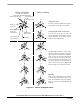
5.4.3 Starting (Back-EMF Acquisition)
The Back-EMF sensing technique enables a sensorless detection of the rotor position, however the drive must
be first started without this feedback. It is caused by the fact that the amplitude of the induced voltage is
proportional to the motor speed. Hence, the Back-EMF cannot be sensed at a very low speed and a special
start-up algorithm must be performed.
In order to start the BLDC motor, the adequate torque must be generated. The motor torque is proportional to
the multiplication of the stator magnetic flux, the rotor magnetic flux and the sine of angle between both
magnetic fluxes.
It implies (for BLDC motors) the following:
1. The level of phase current must be high enough.
2. The angle between the stator and rotor magnetic fields must be in 90deg±30deg.
The first condition is satisfied during the Alignment state by keeping the DC-Bus current on the level which is
sufficient to start the motor. In the Starting (Back-EMF Acquisition) state the same value of PWM duty cycle
is used as the one which has stabilized the DC-Bus current during the Align state.
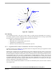
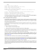
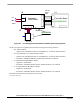
The second condition is more difficult to fulfill without any position feedback information. After the
Alignment state, both the stator and the rotor magnetic fields are aligned (0deg angle). Therefore, the two fast
(faster then the rotor can follow) commutation must be applied to create an angular difference of the magnetic
fields (see Figure 5-9).
The commutation time is defined by the start commutation period (Per_CmtStart).
This allows to start the motor the way that minimal speed (defined by state when Back-EMF can be sensed) is
achieved during several commutation while producing the required torque. Until the Back-EMF feedback is
locked into the Commutation Process (explained in
Section 5.4.2) assures that commutations are done in
advance, so that successive Back-EMF Zero Crossing events are not missed.
After several successive Back-EMF Zero Crossings, the exact commutation times can be calculated. The
commutation process is adjusted. The control flow continues to the Running state. The BLDC motor is then
running with regular feedback and the speed controller can be used to control the motor speed by changing the
PWM duty cycle value.