
User Manual


Control Technique
3-Phase BLDC Motor Control with Sensorless Back-EMF, ADC, Zero Crossing, Rev. 3
22 Freescale Semiconductor
Preliminary
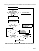
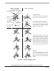
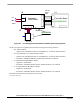
The flow chart explaining the principle of BLDC Commutation control with Back-EMF Zero Crossing Sensing
is shown in
Figure 5-7.
Service of Commutation:
BEMF Zero Crossing
Wait for Per_Toff until phase
missed?
BEMF Zero Crossing
Detected?
BEMF Zero Crossing missed
Service of received BEMF
has commutation
time expired?
Make motor Commutation
Zero Crossing:
corrected setting of
BEMF Zero Crossing
detected between previous
commutations?
Corrective Calculation 1.
Preset commutation
Corrective Calculation 2.
corrected setting of
commutation time
commutation time
has commutation
time expired?
current decays to zero
Commutation Done
No
Yes
Yes
No
No
No
Yes
Yes
No
Yes
Figure 5-7. Flow Chart - BLDC Commutation with Back-EMF Zero Crossing Sensing