
User Manual

Sensorless Commutation Control
3-Phase BLDC Motor Control with Sensorless Back-EMF, ADC, Zero Crossing, Rev. 3
Freescale Semiconductor 21
Preliminary
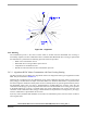
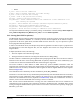
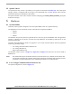
Figure 5-6. Alignment
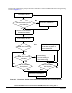
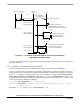
5.4.2 Running
The commutation process is the series of states which is assured when the Back-EMF Zero Crossing is
successfully captured. The new commutation time is calculated after Back-EMF Zero Crossing is captured and
the commutation is performed. The following processes need to be provided:
• BLDC motor commutation service
• Back-EMF Zero Crossing moment capture service
• Computation of commutation times
• Handler for interaction between these commutation processes
5.4.2.1 Algorithms BLDC Motor Commutation with Zero Crossing Sensing
All these processes are provided by new algorithms which were designed for these type of applications within
SDK. They are described in
Section 11.1.
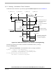
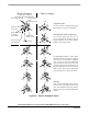
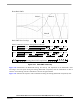
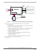
Diagrams aid in explaining how the commutation works. After commuting the motor phases, a time interval
(Per_Toff[n]) is set that allows the shape of the Back-EMF to be stabilized. Stabilization is required because
the electro-magnetic interference and fly-back current in antibody diode can generate glitches that may add to
the Back-EMF signal. This can cause a misinterpretation of Back-EMF Zero Crossing. Then the new
commutation time (T2[n]) is preset and performed at this time if the Back-EMF Zero Crossing is not captured.
If the Back-EMF Zero Crossing is captured before the preset commutation time expires, then the exact
calculation of the commutation time (T2*[n]) is made based on the captured Zero Crossing time (T_ZCros[n]).
The new commutation is performed at this new time.
If (for any reason) the Back-EMF feedback is lost within one commutation period, corrective action is taken to
return regular states.