
User Manual

PWM1 S
At
PWM2 S
Ab
PWM3 S
Bt
PWM4 S
Bb
PWM5 S
Ct
PWM6 S
Cb
electrical angle
I
A
I
B
I
C
60 120
Commutation Commutation
Back-EMF Zero Crossing sensing
3-Phase BLDC Motor Control with Sensorless Back-EMF, ADC, Zero Crossing, Rev. 3
Freescale Semiconductor 17
Preliminary
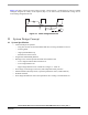
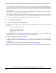
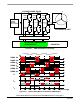
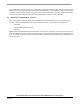
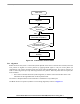
Figure 5-3. BLDC Commutation with Bipolar (Hard) Switching
Figure 5-3 shows that the diagonal power switches are driven by the same PWM signal as shown with arrow
lines. This technique is called bipolar (hard) switching. The voltage across the two energized coils is always
±DC-Bus voltage whenever there is a current flowing through these coils.
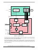
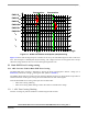
5.3 Back-EMF Zero Crossing sensing
5.3.1 ADC Converter Used for Back-EMF Zero Crossing
The Back-EMF Zero Crossing is detected by sensing the motor non-fed phase “branch“ voltage (u
vi
in
Section 3.5) and DC-bus voltage u
d
utilizing the ADC. (Refer to Section 3.).
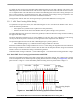
The 56F80x family offers an excellent on-chip Analog-to-Digital converter. Its unique feature set provides an
automatic detection of the signal crossing the value contained in the ADC offset register.
Then the Back-EMF Zero Crossing can be split into two main tasks:
• ADC Zero Crossing Checking
• ADC Zero Crossing Offset Setting to follow the variation of the DC-Bus voltage
5.3.1.1 ADC Zero Crossing Checking
The Zero Crossing for position estimation is sensed using the AD converter.