
User Manual

System Specification
3-Phase BLDC Motor Control with Sensorless Back-EMF, ADC, Zero Crossing, Rev. 3
Freescale Semiconductor 11
Preliminary
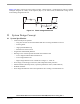
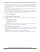
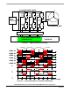
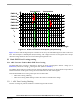
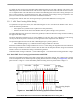
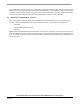
Figure 3-6 shows branch and motor phase winding voltages during a 0-360°electrical interval. Shaded
rectangles designate the validity of the equation (EQ 3-6.). In other words, the Back-EMF voltage can be
sensed during designated intervals.
0 30 60 90 120 150 180 210 240 270 300 330 360 39
0
uVA
uA
Figure 3-6. Phase Voltage Waveforms
4. System Design Concept
4.1 System Specification
• Control technique incorporates
— using AD converter for sensorless Back-EMF Zero Crossing commutation control
— motoring mode
— single speed feedback loop
— both direction of the rotation
• Targeted for 56F80xEVM platforms
• Running on one of three optional board and motor hardware sets
— Low Voltage Evaluation Motor hardware set
— Low Voltage hardware set
— High Voltage hardware set at variable line voltage 115 - 230V AC
• Overvoltage, Undervoltage, Overcurrent, and Temperature Fault protection
• Manual Interface (Start/Stop switch, Up/Down push button control, LED indication)
• PCMaster Interface
• Power Stage Identification with control parameters set according to used hardware set