
User Manual

Target Motor Theory
3-Phase BLDC Motor Control with Sensorless Back-EMF, ADC, Zero Crossing, Rev. 3
10 Freescale Semiconductor
Preliminary
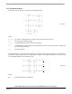
The internal torque of the motor itself is defined as:
T
i
1
ω
----
u
ix
i
x
⋅
xA=
C
∑
θd
dΨ
x
i
x
⋅
xA=
C
∑
== (EQ 3-3.)
where:
T
i
- internal motor torque (no mechanical losses)
ω,θ - rotor speed, rotor position
x - phase index, it stands for A,B,C
Ψ
x
- magnetic flux of phase winding x
It is important to understand how the Back-EMF can be sensed and how the motor behavior depends on the
alignment of the Back-EMF to commutation events. This is explained in the next sections.
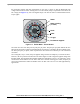
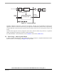
3.5 Back-EMF Sensing
The Back-EMF sensing technique is based on the fact that only two phases of a Brushless DC motor are
energized at a time (see
Figure 3-2). The third phase is a non-fed phase that can be used to sense the
Back-EMF voltage.
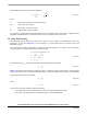
Let us assume the situation when phases A and B are powered and phase C is non-fed. No current passes
through this phase. Assume the following conditions are met:
S
Ab
S
Bt
performingPWMswitching,
u
VA
1
2
---
u
d
+
−
= u
VB
1
2
---
± u
d
=,
i
A
i
B
–= i
C
0= i
C
d 0=,,
u
iA
u
iB
u
iC
++ 0=
(EQ 3-4.)
The branch voltage u
VC
can be calculated when considering the above conditions:
u
VC
3
2
---
u
iC
= (EQ 3-5.)
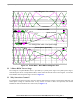
Figure 3-5 illustrates that the branch voltage of phase C, between the power stage output C and the natural
voltage level, can be sensed. Thus the Back-EMF voltage is obtained and the Zero Crossing can be recognized.
The general expression can be found by:
u
Vx
3
2
---
u
ix
= (EQ 3-6.)
where:
xABC,,= (EQ 3-7.)
There are two necessary conditions which must be met:
• Top and bottom switch (in diagonal) have to be driven with the same PWM signal
• No current is going through the non-fed phase used to sense the Back-EMF