
Operating instructions


20
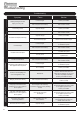
1. Installing the Appliance
Each installation is unique to the property so it is not possible
to give details to suit every setting. The installation must comply
with Building Regulations
†
and be made using "best practice"
construction methods
‡
.
Many fireplace openings have a supporting lintel. Do not remove
without supporting the remaining structure of the building. Do not
support the structure or the flue system with the appliance.
1.1 Take care when installing the appliance. Careless
handling and use of tools can damage the finish and/or
area.
Choose top or rear flue exit, see Diagram 1.
Top
Rear
Hexagonal bolts,
washers and nuts
Black Hex Key
countersunk screws
1
— Fit flue collar and blanking plate to suit.
1.2 Lift the stove into position on the prepared hearth area,
taking care not to damage the hearth finish.
Choose top or rear flue exit.
—Fit flue collar and blanking plate to suit.
—Attach flue collar to top or rear with hexagonal bolts.
—Seal with fire cement.
—Secure blanking plate with the black Hex Key countersunk
screws.
Installation Instructions
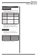
1.3 Top flue pipe installation
Seal Flue Collar
with Fire Cement
Self Tapping Screw
Flue Pipe 915mm (3ft)
Size Part No.
5" 4502
6" 4602
2
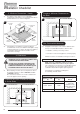
—Level feet using adjustable bolts.
—Connect appliance to the chimney using flue pipe.
3
—Secure pipe to flue collar with self tapping screw.
—Seal the connecting joints with fire cement.
The Flue must be installed in accordance with
manufacturers instructions.
Typical Top Flue Installation
600mm minimum
1000mm maximum
unsupportable weight
To chimney connection as
detailed in building regulations
Flue Pipe 915mm (3ft)
Size Part No.
5" 4502
6" 4602
135 Elbow
Size Part No.
5" 4512
6" 4612
4
† England and Wales – Document J / Scotland - Part
F/Document J (Republic of Ireland only)
‡ the latest edition of BS 8303, BS EN 15287, BS
7566