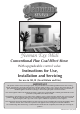
Yeoman Exe Midi Conventional Flue Coal Effect Stove With upgradeable control valve Instructions for Use, Installation and Servicing For use in GB, IE (Great Britain and Eire) IMPORTANT This product contains a Heat resistant glass panel. This panel should be checked during Installation and at each servicing interval.
CONTENTS COVERING THE FOLLOWING MODELS: YM-N9171FL / YM-N9171LC YM-P9171FL / YM-P9171LC PAGE Appliance commissioning checklist 3 user instructions 4 Installation Instructions 9 Technical Specification 9 Site Requirements 10 Installation 11 Commissioning 14 Servicing Instructions 15 Servicing Requirements 15 Fault Finding 15 How to replace parts 17 Basic spare parts list 21 2
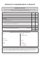
APPLIANCE COMMISSIONING CHECKLIST Important NOTICE Explain the operation of the appliance to the end user and hand the completed instructions to them for safe keeping as the information will be required when making any guaranteed claims. FLUE CHECK Pass 1. Flue is correct for appliance 2. Flue flow test 3. Spillage test Fail GAS CHECK 1. Gas soundness & let by test 2. Standing pressure test mb 3.
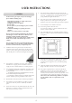
USER INSTRUCTIONS 1. general In the event of a gas escape, or if you can smell gas, please take the following steps: —Immediately turn off the gas supply at the meter/ emergency control valve. —Extinguish all sources of ignition. —Do not smoke. —Do not operate any electrical light or power switches (On or Off). —Ventilate the building(s) by opening doors and windows. —Ensure access to the premises can be made.
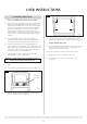
USER INSTRUCTIONS YELLOW FLAMES APPEAR WHEN THE STOVE HAS REACHED SUFFICIENT HEAT (10 TO 20 MINUTES). IF THE STOVE IS EXTINGUISHED OR GOES OUT DURING USE WAIT 3 MINUTES BEFORE ATTEMPTING TO RELIGHT. 2. Lighting the STOVE 2.1 The control valve is on the right-hand side at the foot of the stove. It has two controls: —The right-hand knob controls the pilot ignition —The left-hand knob controls the main burner 2.2 3.
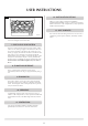
USER INSTRUCTIONS 4 5. cleaning the stove Advice on Handling and Disposal of Fire Ceramics 5.1 The fuel effect logs and embers in this stove are made from Refractory Ceramic Fibre (RCF). Protective clothing is not required when handling these articles, but we recommend you follow normal hygiene rules of not smoking, eating or drinking in the work area and always wash your hands before eating or drinking.
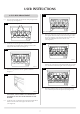
HEADING USER INSTRUCTIONS 8 6. Fuel bed arrangement 6.1 Place the flame baffle onto the burner and push against the rear tray lip (see Diagram 5). 5 Spacer brackets Heat shield 6.5 Place five of the loose round coals on the front coal so they lean against the flame baffle, in between the fingers. Place the two rectangular coals against the reflector panels, one either side, behind the front row of loose coals (see Diagram 9). AR0359 6.
USER INSTRUCTIONS 11 12. INSTALLATION DETAILS Make sure your installer completes the Appliance Commissioning Checklist on page 3. This records essential details of this stove. In all correspondence, always quote the Model and Serial Number. 13. HOT SURFACES This stove becomes hot during normal use. You must use a suitable fire guard to protect children, the elderly and the infirm. AR0364 6.8 Replace the glass frame using the 6 x frame fixing screws (see Diagram 4) and close door. 7.
INSTALLATION INSTRUCTIONS TECHNICAL SPECIFICATION Covering the following models: Yeoman Exe Midi YM-N9171FL / YM-N9171LC YM-P9171FL / YM-P9171LC Model Gas CAT. Gas Type Working Pressure NOX Class Aeration Yeoman Exe Midi YM-N9171FL/LC I2H Natural Gas G20 20 mbar 5 1 x 7.5mm 260 Yeoman Exe Midi YM-P9171FL/LC I3P LPG Propane G31 37 mbar 5 1 x 13.5mm 110 Injector Gas Rate m³/h Input kW (Gross) Country High Low 0.435 4.6 Gross 2.5 Gross GB, IE 0.170 4.4 Gross 2.
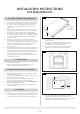
INSTALLATION INSTRUCTIONS SITE REQUIREMENTS 1 1. Flue and Chimney Requirements 1.2 1.3 1.4 1.5 1.6 The chimney or flue system must comply with the rules in force, and must be a minimum of 127mm (5") in diameter. The minimum effective height of the flue or chimney must be 3 metres (10ft). Any horizontal flue run from the rear outlet should not exceed 100mm from the back of the appliance. The chimney or flue must be free from any obstruction.
INSTALLATION INSTRUCTIONS INSTALLATION IMPORTANT: ENSURE THAT THE APPLIANCE IS CORRECTLY ADJUSTED FOR THE GAS TYPE AND CATEGORY APPLICABLE IN THE COUNTRY OF USE. REFER TO DATA BADGE AND TECHNICAL Specification AT THE FRONT OF THIS BOOKLET. FOR DETAILS ON CHANGING BETWEEN GAS TYPES REFER TO SECTION 11 PAGE 20 . 2.7 The stove is fitted with the Gazco Flue Sure System, which will act to cut off the gas supply to the appliance in the event of incorrect operation of the flue.
INSTALLATION INSTRUCTIONS INSTALLATION 3.5 Check the pull of the flue system by applying a lighted smoke pellet to the flue system opening. If there is a definite flow into the chimney, proceed with the installation, if not warm the chimney for a few minutes. 5 Turn rose to open door IF THERE IS STILL NO DEFINITE FLOW, THE FLUE MAY REQUIRE ATTENTION - SEEK EXPERT ADVICE. 3.6 3.7 The flue system may now be connected to the stove, ensure that all joints are sealed with a suitable fire resistant sealant.
INSTALLATION INSTRUCTIONS INSTALLATION 11 8 AR0362 AR0360 4.8 4.11 Place four of the loose round coals behind the first row so that they sit on the fingers, the two outer coals should touch the rectangular coals (see Diagram 12). Place the log retainer in the two guides as shown in Diagram 9. 12 9 AR0363 AR2076 4.12 Place the remaining three coals behind the centre row so that they touch the back panel (see Diagram 13).
INSTALLATION INSTRUCTIONS COMMISSIONING 1. COMMISSIONING After connecting the gas pipe to the stove: 1.1 PURGE THE SUPPLY PIPE to dispel any debris that might block the controls. 1.2 Connect the gas supply to the 8mm compression elbow at the right-hand rear corner of the stove (see Diagram 1). 1 AR0934 1.3 Connect a suitable pressure gauge to the test point on the inlet fitting. 1.4 Turn on the gas supply. 1.5 Light the stove and check all gas joints for leaks. 1.
SERVICING INSTRUCTIONS SERVICING REQUIREMENTS/ FAULT FINDING CHARTS 1.3 1. SERVICING REQUIREMENTS Special checks: —Clean any lint or fluff from the pilot - pay particular attention to the aeration hole in the side of the pilot. —Clean away any fluff or lint from under the burner. —Check that the spark gap on the pilot is correct. 1.4 Correct any faults found during the initial tests and then re-commission the appliance conducting the usual safety checks. 1.
Replace the combined lead and piezo, retry. No Is the electrode wire detached from the piezo in the valve? No Replace the electrode. Yes Yes Yes No No Correct and retry. Reset the pilot burner. Is the valve being operated correctly? Yes Replace the piezo and gas valve and retry. No Remove the electrode lead from the piezo. Operate the valve. Does a spark jump from the piezo to the valve body? Check for defective or damaged control knob spindle or cam operation.
SERVICING INSTRUCTIONS REPLACING PARTS 2.4 1. GENERAL 1.1 All main components can be replaced with the stove in place but it is essential to turn off the gas supply at the isolation device before proceeding. For information on the handling and disposal of fire ceramics please refer to User Instructions, Section 5, Cleaning the Fire. Remove the two screws at the back of the firebox and lift the burner unit clean (see Diagram 3). 3 ENSURE THE APPLIANCE IS COLD BEFORE STARTING WORK ON IT. 2.
SERVICING INSTRUCTIONS REPLACING PARTS 3.3 The pilot unit can now be removed by undoing the two screws (see Diagram 6). 8 6 AR0916 AR1445 3.4 Reassemble in reverse order, do not overtighten. NOTE: SPECIAL CARE SHOULD BE TAKEN WHEN REPLACING THE THERMOCOUPLE TO THE BACK OF THE GAS VALVE TO ENSURE THAT THE SENSOR WIRES FOR THE GAZCO FLUE SURE SYSTEM ARE NOT DISCONNECTED. 4.3 Replace with a new ignition lead following the same route as the old one. Replace the valve cover and the pilot assembly. 4.
SERVICING INSTRUCTIONS REPLACING PARTS 6.3 7.2 Undo the single screw that secures the left hand side of the control cover (see Diagram 10). 10 Undo the magnetic valve-retaining nut from the back of the control valve, gently tap out the magnetic valve and replace with a new unit. Replace the retaining nut and tighten (see Diagram 12). 12 A AR0915 6.4 AR0915 To release the right hand side of the control cover insert the narrow blade screwdriver into the slot shown in Diagram 11.
SERVICING INSTRUCTIONS REPLACING PARTS 9.4 9. Gazco flue sure system 9.1 Open the door and remove the ceramics, placing them carefully to one side. Undo the two screws in the back of the firebox and carefully withdraw the bracket (see Diagram 14). Feed the cable back through the hole as you replace the bracket. When the bracket is located correctly it will sit flush with the back panel without force being required. If not positioned correctly the bracket will sit at an angle (see Diagram 17).
SERVICING INSTRUCTIONS REPLACING PARTS 13. BASIC Spares List 11. Changing between gas types In order to change between gas types it will be necessary to change the following items: - NG COMPONENT Pilot Unit Control Valve** Main Injector Aeration Plate Data Badge The relevant parts can be ordered from Gazco. Always quote the appliance type and serial number when ordering spare parts.
SERVICE RECORDS 1st Service Date of Service:. . . . . . . . . . . . . . . . . . . . . . . . . . . . . . . . . Next Service due:. . . . . . . . . . . . . . . . . . . . . . . . . . . . . . . . Signed:. . . . . . . . . . . . . . . . . . . . . . . . . . . . . . . . . . . . . . . . Retailer’s Stamp/Gas Safe Registration Number 2nd Service Date of Service:. . . . . . . . . . . . . . . . . . . . . . . . . . . . . . . . . Next Service due: . . . . . . . . . . . . . . . . . . . . . . . . . . . . . . .
A division of Stovax Ltd Falcon Road, Sowton Industrial Estate, Exeter, Devon, England EX2 7LF Tel: (01392) 474500 Fax: (01392) 219932 E-mail: yeoman@stovax.com www.yeoman-stoves.co.