
Technical data

PAGE 51
Talkmaster XT ® Software
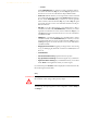
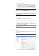
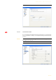
FIG. 28 SEQUENCE OF EVENTS FOR THE EXAMPLE 1
TTL Pin as Output
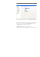
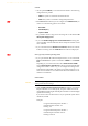
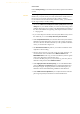
FIG. 29 TTL PIN AS OUTPUT
If a TTL Pin is configured as Output, the event is signalised as change of volt-
age on the TTL Pin from 0V to+3.3V.
Under Positive edge you can select one of the following Function Codes:
– Fixed Low: The TTL Pin is set to 0V permanently.
– Fixed High: The TTL Pin is set to +3.3V permanently.
– Connection Status: Via this function you can signal the connection
status of a line. Select the connection status under Connection Status.
The following options are possible:
– Disconnect
– Calling
– Incoming call
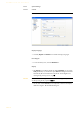
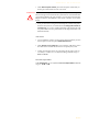
ATTENTION Please pay attention to the maximum switch current of 10 mA respectively
the maximum switch voltage of 3.3V per TTL output.
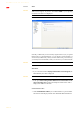
1
5
6
9
9-pol. SUB-D connector
to b-line XT
(TTL/RELAY)
Switch is opened:
Pin 2 = TTL 1 is on +3.3 V (via internal 10 KOhm series resistance)
Switch is closed:
Pin 2 =TTL 1 is set to 0V (Pin 5):
Existing connection is dropped
Switch is opened:
Pin 2 =TTL 1 is set to +3.3V:
Incoming call is accepted.
Switch
!