
Technical data


PAGE 21
Putting the system into operation
3.5 Operating modes of the system
The following figures show the system in the different operating modes and
their respective cablings.
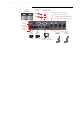
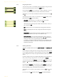
3.5.1 POTS operating mode
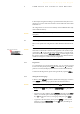
The minimal wiring for the operation with an analogue telephone line is pic-
tured in Fig. 4. Via the PHONE Interfaces up to two POTS telephones can be
connected for PRETALK if required.
FIG. 4 MINIMUM WIRING IN POTS OPERATING MODE
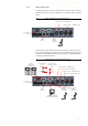
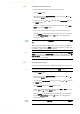
The maximum wiring with all options is shown in Fig. 5. The LAN interface
allows the connection with a PC with Talkmaster XT
®
Software. In total,
three PCs with Talkmaster XT
®
Software can access the system. Via the
RS232 interface you can connect two b-line XT Keypads.
ATTENTION Earthing
If the POTS interfaces are in operation, the system must be earthed via earth-
ing screw for EMC reasons. If the earthing is not carried out, the Audio signal
can be faulty on the caller’s side (humming).
ATTENTION Connection of a POTS Telephone
Please note that the PHONE interfaces are implemented as 6-pole Western
sockets. Standard telephones with 4-pole Western connectors must not be
used because otherwise the contacts in the socket will be destroyed.
!
!
Power supply
interface
POTS
interface
Analogue Audio 1/AES/EBU Input
Analogue Audio 1/AES/EBU Output
Telephone
Option:
Earthing!
Use 6-pole
Western connectors
only!