
Technical data


PAGE 107
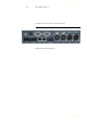
Interfaces
A2.4 Control Interface
A2.4.1 LAN interface
Please see A2.1.3, Page 103.
A2.4.2 Keypad 1,2 interface
To this interface you can connect an external b-line XT Keypad to control the
system. If you want to connect two Keypads simultaneously, you need an
adapter cable. Alternatively, if you don’t want to use the LAN interface to
connect a PC to b-line XT, you can also use the RS232 interface. To connect a
PC you need a 1:1 connecting cable, in which Pin 2 and Pin 3 are not crossed.
Additionally, Pin 5 GND must be connected. The remaining Pins are not used.
A2.4.3 TTL/RELAY interface
Via this interface external control signals can be used.
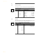
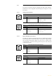
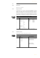
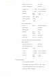
TAB. 15 PIN ASSIGNMENT: KEYPAD INTERFACE (RS232)
Socket: SUB-D (9 pin)
Pin Signal Electrical characteristics
1not usedType:DCE
a
Level: V.24
Data rate: 38400 Baud
Range: max. 15 m
Protocol: 1 Start bit
8 Data bits
1 Stop bit
a DCE = Data Communication Equipment: to connect a PC a 1:1 cable is required
2 TXD Keypad 1 OUT
3RXD Keypad 1IN
4not used
5GNDEarth
6not used
7RXD Keypad 2 IN
8 TXD Keypad 2 OUT
9not used
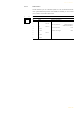
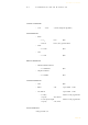
TAB. 16 PIN ASSIGNMENT: TTL/RELAY INTERFACE (TTL/RELAY)
Socket: SUB-D (9 pin)
Pin Signal Electrical characteristics
1 TTL 1 IN/OUT
Capacity of the TTL inputs/outputs:
Maximum voltage: 3.3 V
Maximum current: 10mA
Capacity of the relays:
Maximum voltage: 48V
Maximum current: 200mA
2 TTL 2 IN/OUT
3 TTL 3 IN/OUT
4TTL 4IN/OUT
5GND
6Relay 1a
7Relay 1b
8Relay 2a
9Relay 2b
5
1
9
6
5
1
9
6