
Data Sheet


Copyright 2015-2021 EAI
4 / 7
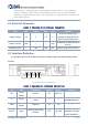
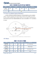
2.4 Data Communication
With a 3.3V level serial port (UART), users can connect the external system and the
product through the physical interface. After that, you can obtain the real-time scanned
point cloud data,device information as well as device status.The communication protocol of
parameters are as follows:
CHART 4 YDLIDAR X2 SERIAL SPECIFICATION
Item
Min
Typical
Max
Unit
Remarks
Baud rate
/
115200
/
bps
8-bit data bit,1 stop bit,
no parity
High Signal Level
2.4
3.3
3.5
V
/
Low signal Level
0
0
0.6
V
/
2.5 Motor Control
X2 has its own motor driver with motor speed control function. The peripheral can
control the X2 motor by inputting control signals through the M_CTR pin in the interface.
M_CTR is the motor speed control signal, which can be adjusted by voltage and can also
be debugged by PWM wave. The higher the voltage/the greater the PWM duty cycle, the
higher the motor speed.
Among them, the PWM signal of M_CTR has the following requirements:
CHART 5 YDLIDAR X2 MOTOR PWM SIGNAL SPECIFICATION
Item
Min
Typical
Max
Unit
Remarks
PWM
frequency
/
10
/
KHz
PWM is a square wave
signal
Duty cycle
range
0
35%
100%
/
The larger the duty cycle,
the faster the speed
2.6 Optical Characteristic
X2 uses an infrared laser that meets FDA Class I eye safety standards. The laser and
optical lens finish the transmission and reception of the laser signal to achieve high-
frequency ranging while working. To ensure system ranging performance, please keep the
laser and optical lens clean. The detailed optical parameters are as follows: