DOC#:01.13.000202 X2 USER MANUAL www.ydlidar.com Shenzhen EAI Technology Co.,Ltd.
CONTENTS 1 YDLIDAR X2 LIDAR DEVELOPMENT KIT ............................................ 1 1.1 Development Kit ........................................................................................ 1 2 USAGE UNDER WINDOWS ..................................................................... 1 2.1 Device Connection .................................................................................. 1 2.2 Driver Installation ....................................................................................
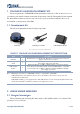
1 YDLIDAR X2 LIDAR DEVELOPMENT KIT The development kit of YDLIDAR X2 lidar (hereinafter referred to as X2) is an accessory tool provided for performance evaluation and early development of the X2. Through the X2 development kit, and with the evaluation software, users can observe point cloud data scanned by X2 on your environment or development on the SDK. 1.
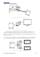
FIG 2 YDLIDAR X2 DEVICE CONNECTION STEP 1 FIG 3 YDLIDAR X2 DEVICE CONNECTION STEP 2 Connect the adapter board with X2 first, then connect the USB cable to the USB port of the adapter board and the PC. Note that the Type-C interface of the USB cable is connected to the USB_DATA of the USB adapter board, and the X2 enters the idle mode after being powered on. The motor does not rotate. The drive current of USB interface of some development platforms or PC is not sufficient.
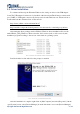
2.2 Driver Installation To evaluate and develop the X2 under Windows, the serial port driver of the USB adapter board. The USB adapter board need to be installed of this kit adopts CP2102 chip to realize serial port (UART) to USB signal conversion. Its driver can be downloaded from our official website or downloaded from the official website of Silicon Labs. https://www.ydlidar.com/dowfile.html?id=97 http://cn.silabs.
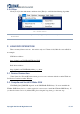
Expand [Port] to see the serial port name corresponding to the identified USB adapter, that is, the driver installation is successful. The following figure shows COM3. (Note that the port must be checked in case of X2 and PC interconnection). FIG 7 YDLIDAR X2 DRIVER INSTALLATION CHECK 2.3 Evaluation Software Usage YDLIDAR provides Point Cloud Viewer, a point cloud data visualization software LidarViewer for X2 real-time scanning. Users can intuitively observe the X2 scanning effect chart.
If the connection is correct, you will see the following screen: FIG 9 POINTCLOUD VIEWER INTERFACE 2.3.1 Start Scanning Click to start scanning and display the environment point cloud, the upper left corner displays the angle & distance information of the red line position (unit: mm). Click shown below: to stop it.
2.3.2 Data Storage During lidar scanning, click [File] in the main menu, select [Export to Excel], and save point cloud data according to the prompts. Then the system will save the point cloud information scanned in a circle in Excel format. FIG 11 SAVE DATA 2.3.3 Display Mean and Standard Deviation Click [Tools] in the main menu, then select [Mean And STD] - [View].
FIG 14 RECORD AND PLAY The main window is displayed To record lidar data, click as follows: to start recording, and click In non-scanning mode, click to stop recording. to start play. The play process is as follows: FIG 15 PLAY PROCESS 2.3.5 Debug Click [Tools] in the main menu, and then select [DebugON] to output the raw lidar data to the "viewer_log.txt" and "viewer_log_err.txt" files.
2.3.6 Filter Click [Tools] in the main menu, and then select [Filter] to add lidar data filtering algorithm. FIG 17 FILTER SETTING Note: For more functions of LidarViewer, please click [Help], select [More Information], and learn more about how to use it. 3 LINUX ROS OPERATION There are many Linux versions,this article only uses Ubuntu 18.04, Melodic version ROS as an example. SDK driver address: https://github.com/YDLIDAR/YDLidar-SDK ROS driver address: https://github.com/YDLIDAR/ydlidar_ros_driver 3.
$ git clone https://github.com/YDLIDAR/YDLidar-SDK.git $ cd YDLidar-SDK/build $ cmake .. $ make $ sudo make install 3.3 ROS Driver Installation 1) Cloning GitHub's YDlidar ROS Driver Package: $ git clone https://github.com/YDLIDAR/ydlidar_ros_driver.git ydlidar_ws/src/ydlidar_ros_driver 2) Build the Ydlidar_ROS_Driver software package: $ cd ydlidar_ws $ catkin_make 3) Package environment Settings: $ source ./devel/setup.sh Note: Add permanent workspace environment variables.
$ roslaunch ydlidar_ros_driver X2.launch 3.5 RVIZ View Scan Results Run the launch file and open rviz to view the X2 scan results, as shown in the figure below: $ roslaunch ydlidar_ros_driver lidar_view.launch Note: Take G4 as an example by default, if use other types of lidar, need to change lidar.launch in lidar_view.launch file to the corresponding **.launch file. (If X2 lidar is used, it needs to be changed to X2.launch) FIG 18 YDLIDAR X2 RVIZ 3.
FIG 19 X2.LAUNCH FILE Note: For more information about the file contents, please refer to https://github.com/YDLIDAR/ydlidar_ros_driver#configure-ydlidar_ros_driver-internal-parameter 2) The X2 lidar coordinates follow the right-hand rule within ROS, with an angle range of [-180, 180]. "angle_min" is the start angle, and "angle_max" is the endangle. The specific scope needs to be modified according to actual use.
4 CAUTION 4.1 Ambient Temperature When the working environment temperature of X2 is overhigh or overlow, it will affect the accuracy of the distance measuring system. It may also damage the structure of the scanning system and reduce the service life of the X2 lidar. Avoid using in high temperature (>50 degrees celsius) and low temperature (<0 degrees celsius) conditions. 4.
5 REVISE Date Version Content 2017-12-05 1.0 Composing a first draft 2018-01-22 1.1 Added auxiliary power connection method, document description, configuration description, and power supply requirements 2018-04-03 1.2 Adapt to PointCloudViewer2.0 client 2021-08-02 1.