
Instruction manual


66
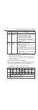
V7 Standard Control I/O Instances
V7 Standard control I/O instances are for DeviceNet-compatible Invert-
ers only. All of the Inverter’s I/O functions can be used in addition to
the functions supported by the Extended I/O Instances.
V7 Standard control I/O instances can be used with Yaskawa Inverters
only. They cannot be used with other companies’ DeviceNet-compati-
ble Inverters.
Eight bytes are used for input data and eight bytes are used for output
data.
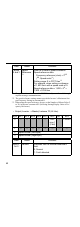
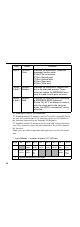
• Input (Master → Inverter) Instance 101 (65 Hex)
Data Name Contents
Byte 0 Function
Code
Indicates the MEMOBUS (response
message) function code.
00 Hex: Do not execute.
03 Hex: Normal read
10 Hex: Normal write
83 Hex: Read error
90 Hex: Write error
Bytes
1 and 2
Register
Number
Indicates the MEMOBUS register num-
ber in the executed process. These
bytes will contain the MEMOBUS error
code if a read or write error occurred.
Bytes
3 and 4
Register
Data
Indicates the read data when executing
a MEMOBUS READ command.
Shows “00, 00” if an attempt is made to
write the same data to the same ad-
dress; the WRITE command will not be
executed.
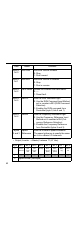
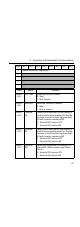
Byte Bit 7 Bit 6 Bit 5 Bit 4 Bit 3 Bit 2 Bit 1 Bit 0
0 --- Termi-
nal S7*
Term i-
nal S6*
Te rm i-
nal S5*
Term i-
nal S4
Te rm i-
nal S3
Run
Rev
Run
Fwd
1Termi-
nal P2
Te rm i-
nal P1
Term i-
nal
MA*
--- --- --- Fault
Reset
Exter-
nal
Fault
2 Speed Reference (Low Byte)