
Instruction manual


6. Operating with DeviceNet Communications
65
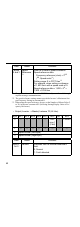
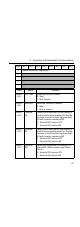
• Input (Master → Inverter) Instance 100 (64 Hex)
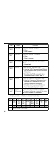
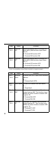
• Output (Inverter → Master) Instance 150 (96 Hex)
Byte Bit 7 Bit 6 Bit 5 Bit 4 Bit 3 Bit 2 Bit 1 Bit 0
0 Function Code
1 Register Number (High Byte)
2 Register Number (Low Byte)
3 Register Data (High Byte)
4 Register Data (Low Byte)
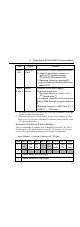
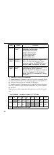
Data Name Contents
Byte 0 Function
Code
Set the MEMOBUS (command mes-
sage) function code.
03 Hex: Read
10 Hex: Write
00 Hex: Do not execute.
Bytes
1 and 2
Register
Number
Set the Inverter’s MEMOBUS register
number.
Bytes
3 and 4
Register
Data
Set the write data when executing a ME-
MOBUS WRITE command.
Byte Bit 7 Bit 6 Bit 5 Bit 4 Bit 3 Bit 2 Bit 1 Bit 0
0 Function Code
1 Register Number (High Byte)
2 Register Number (Low Byte)
3 Register Data (High Byte)
4 Register Data (Low Byte)