
Instruction manual


6. Operating with DeviceNet Communications
61
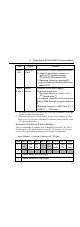
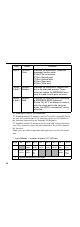
* 1. The speed scale can be set with AC/DC Drive object attribute 16 through
explicit message communications.
* 2. When using the Speed Actual monitor, always set the Number of Motor
Poles (2 to 39) in Inverter constant n035 (Selecting Setting/Display Units
of Frequency Reference).
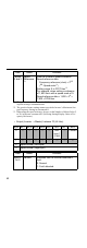
Extended I/O Instance (Factory Setting)
This is a standard I/O instance type defined in DeviceNet’s AC Drive
Profile and it is the initial factory setting for I/O instances. Four bytes
are used for input data and four bytes are used for output data.
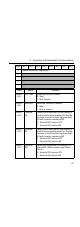
• Input (Master → Inverter) Instance 21 (15 Hex)
Byte 0,
bit 2
Running 1
(Fwd)
Indicates the Inverter’s operating status.
0: Stopped, operating in reverse, or
applying DC injection braking
(Reverse RUN command ON).
1: Operating forward or applying DC
injection braking (Reverse RUN com-
mand OFF).
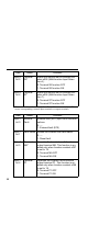
Bytes
2 and 3
Speed
Actual
Indicates the Inverter’s speed.
Monitored speed data:
Monitored frequency (r/min) × 2
SS
(
SS
: Speed scale
*1
)
For example, when the monitored speed
data is 03E8 Hex and the speed scale is
0:
Monitored frequency = 03E8 Hex/ 2
0
=
1,000/ 2
0
= 1,000 r/min.
Byte Bit 7 Bit 6 Bit 5 Bit 4 Bit 3 Bit 2 Bit 1 Bit 0
0 --- Net
Ref
Net
Ctrl
--- --- Fault
Reset
Run
Rev
Run
Fwd
1 --- --- --- --- --- --- --- ---
2 Speed Reference (Low Byte)
3 Speed Reference (High Byte)
Data Name Contents