
Instruction manual


9. Fault Diagnosis
217
Note: To display or clear the fault history, refer to page 52.
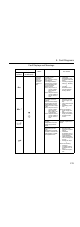
Fault Display Inverter
Status
Description Causes and Correc-
tive Actions
Digital
Operator
RUN (Green)
ALARM (Red)
Protective
Operation
Output is
turned OFF
and motor
coasts to a
stop.
CPF-05
AD converter fault was
detected.
Cycle power.
If the fault remains, re-
place the Inverter.
CPF-06
• Option card connec-
tion fault
• A non-correspond-
ing option card is
connected.
Remove power to the In-
verter. Check the con-
nection of the Digital
Operator. Verify Soft-
ware Version No. (n179).
CPF-07
Operator control circuit
(EEPROM or AD con-
verter) fault
Cycle power after check-
ing the Digital Operator
is securely mounted. If
the fault remains, re-
place the Digital Opera-
tor or Inverter.
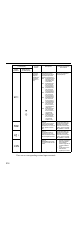
OPR (Operator connect-
ing fault)
Cycle power. If the fault
remains, replace the In-
verter.
Stops ac-
cording to
constant
STP (Emergency stop)
The Inverter stopped ac-
cording to constant n005
after receiving the emer-
gency stop fault signal.
Check the external cir-
cuit (sequence).
FBL (PID feedback loss
detection)
PID feedback value
dropped below the de-
tection level. When PID
feedback loss is detect-
ed, the Inverter operates
according to the n136
setting.
Check the mechanical
system and correct the
cause, or increase the
value of n137.
Communications have
not been established
with the DeviceNet Mas-
ter.
Check the status of the
DeviceNet communica-
tions indicators.
Protective
Operation
Output is
turned OFF
and motor
coasts to a
stop.
• Insufficient power
supply voltage
• Control power sup-
ply fault
• Hardware fault
Check the following:
• Power supply volt-
age
• Main circuit power
supply connections
• Terminal screws:
Loose?
• Control sequence.
• Replace the Inverter.
or
(OFF)