
Instruction manual

6. Operating with DeviceNet Communications
113
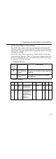
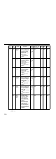
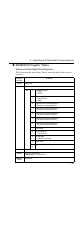
01 10 Input
Voltage
Indicates the
Inverter’s input
voltage.
Minimum units: V/
2
VS
VS
: Voltage scale
(attribute 1B)
--- 00C8 (200
V) or 0190
(400 V)
OK --- Word
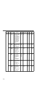
11 Output
Voltage
Indicates the
Inverter’s output
voltage.
Minimum units: V/
2
VS
VS
: Voltage scale
(attribute 1B)
--- 0000 OK --- Word
12 Accelera
tion
Time
Sets or references
the Inverter’s Ac-
celeration Time 1
(n019).
Minimum units: ms/
2
TS
TS
: Time scale (at-
tribute 1C)
0 to
6,000
s
2710 (10.0
s)
OK OK Word
13 Decelera
tion
Time
Sets or references
the Inverter’s De-
celeration Time 1
(n020).
Minimum units: ms/
2
TS
TS
: Time scale (at-
tribute 1C)
0 to
6,000
s
2710 (10.0
s)
OK OK Word
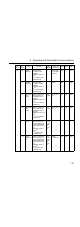
14 Low Spd
Limit
Sets or references
the Inverter’s Fre-
quency Reference
Lower Limit (n034).
(See notes 2 and
3.)
Minimum units: r/
min/2
SS
SS
: Speed scale
(attribute 16)
0 to
110%
of the
max.
fre-
quen-
cy
0000 OK OK Word
15 High
Spd Lim-
it
Sets or references
the Inverter’s Fre-
quency Reference
Upper Limit (n033).
(See notes 2 and
3.)
Minimum units: r/
min/2
SS
SS
: Speed scale
(attribute 16)
0 to
110%
of the
max.
fre-
quen-
cy
0708
(1,800 r/m)
OK OK Word
In-
stance
At-
tribute
Name Contents Setting
Range
Factory Set-
ting (Hex)
Read Write Size