7 ■■■■■ ■ ■■■■ Save This Manual for Future Reference YARDMAX� Walk-Behind Blower Operator 1 s Manual MODEL NUMBER YF1565 SERIAL NUMBER PURCHASE DATE Both model number and serial number may be found on the main label. (See Page 2, Figure 1) You should record both of them in a safe place for future use. READ AND UNDERSTAND THE ENTIRE MANUAL BEFORE OPERATING MACHINE. FAIL URE TO COMPLY WITH THE SAFETY INSTRUCTIONS IN THE MANUAL MAY RESULT IN PERSONAL INJURY.
7 ■■■■■ ■ ■■■■ Your new YARDMAX® walk-behind blower offers quality MAX Performance, MAX Value, MAX Support that's YARDMAX proper use and care, it is designed to give you many .J .J .J .J .J .J construction, and is easy and safe to operate. With years of dependable service.
7 ■■■■■ Walk-Behind Blower » Operator's Manual A WARNING Carefully read through this entire operator's manual before using your new unit. Pay attention to all cautions and warnings. This machine is a gasoline engine driven walk-behind blower. It is a durable, versatile and efficient machine, and MODEL AND SERIAL NUMBERS For future reference, record both the model number and the serial number (See Figure 1) as well as date and place of purchase.
7 ■■■■■ ■ SUPPORT Have questions about your YARDMAX equipment? Call us at 847-327-0566 or 844-YARDMAX, email us at support@yardmax.com, or contact us via your favorite social media site. SPECIFICATIONS Model Number Displacement Max. Air Volume Max. Air Speed Impeller Diameter SwivelCaster Diameter Rear Wheel Diameter Engine Power Type Starting System Engine Torque Fuel Tank Capacity YF1565 209cc 1200CFM 150 MPH 13" 8" 12" YARDMAX Gas Recoil 9.14 lb-ft (12.4 N.m} 0.68 gallons (2.6L) OilCapacity 16.
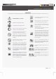
7 ■■■■■ Walk-Behind Blower » Operator's Manual SYMBOLS The rating plate on your machine may show symbols. These represent important information about the product or instructions on its use. & {) (t) 0 1 ..T eo ... e DANGER! WARNING! or CAUTION! aft (!)o,. Read these instructions carefully. • Wear approved hearing protection. � Wear eye protection with side shields marked to comply with ANSI Z87.1. Do not touch parts that are hot from operation. Serious burns may result.
7 ■■■■■ ■ ■■■■ SAFETY The definitions below give the level of severity for each signal word. A DANGER This symbol points out important safety instructions. This machine was built to be operated according to the safe operation practices in this manual. As with any type of power equipment, carelessness or error on that part of the operator can result in serious injury. This machine is capable of amputating fingers, hands, toes and feet and throwing foreign objects.
■■■■■ Walk-Behind Blower » Operator's Manual INSPECT YOUR MACHINE Take precautions when using to reduce the chance of serious in working order. Make sure all nuts, bolts, etc., are securely tightened. When refilling or draining the fuel tank, use an approved fuel storage container while in a clean, well-ventilated outdoor area.
7 ■■■■■ ■ ■■■■ SPECIFIC SA.FETY RULES Identify hazards and take preventive steps to avoid accidents and minimize risk. Possible hazards include, but are not limited Never leave the operating position when the engine is running. Always shut down the engine, and ensure the engine is switched to, moving parts, thrown objects, weight of the machine and components, and the operating environment.
7 ■■■■■ Walk-Behind Blower » Operator's Manual sealed by the manufacturer or distributor. Only a qualified service technician may adjust parts that increase or decrease governed of any moving parts. Parts that are broken or worn down that may affect the machine's operation. If damage or worn parts are engine speed. identified, they should be repaired before use. Many accidents are caused by poorly maintained equipment.
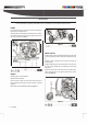
7 ■■■■■ ■■■■ ■ ASSEIMBLY This walk-behind blower was partially assembled at the factory. To assemble your machine follow the below instructions. FRAME Insert the end of the front swivel caster tube into the opening of the frame tube, and align the holes. Attach the tubes to the engine deck with M8x40 bolt, arc washer, spring washer and lock nut in four places. Tighten securely using two 13mm wrenches.
7 ■■■■■ Walk-Behind Blower UPPER HANDLE � NOTE » Operator's Manual THROTTLE CONTROL LEVER There are two positions in which the handle can be attached - a high position and a lower position. Hook the upper handle tabs into the holes on the frame tube (See Figure 5, illustration1). Use the bottom hole for the lower handle position. Use the middle hole for the high handle position. Mount the throttle control lever onto the right upper handle with M5x25 screw and lock nut.
7 ■■■■■ FLOW ANGLE ADJUSTMENT CONTROL CABLE ■ FRONT DISCHARGE CHUTE Attach the Z type end of the cable into the lever as shown. (See Figure 7, illustration 1) Secure the buckle on the cable onto the upper handle. (See Figure ■■■■ � NOTE The front discharge chute is used to redirect the air flow to the front of the blower. Attach it when needed. 7, illustration 2) Secure the cable on the frame tube with cable clamp.
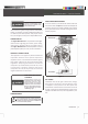
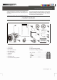
7 ■■■■■ Walk-Behind Blower » Operator's Manual KNOW YOUR MACHINE FEATURES ANID CONTROLS l•Hffi05«@®■3M§ •--------------� lift\Hi¥%i: Intake Guard Upper Handle Frame Tube Front Discharge Chute lii·lllftbtildi§ Discharge Chute Know Your Machine I 12
7 ■■■■■ ■ ■■■■ Air Cleaner Muffler Spark Plug Plffltiii§ ©Ni .;:--___, "'"'----"=� Carburetor I \ --4i•lif.
7 ■■■■■ Walk-Behind Blower » Operator's Manual Throttle Control Lever )) Regulates the speed of engine. Moving towards FAST9 to speed up the engine. Moving towards LOW-A to lower the engine speed. Flow Angle Adjustment Control Lever )) Adjusts the direction of air flow between 7 positions. Fan Housing )) Contains the fan. Flow Angle Adjustment Index Lever )) Recoil Starter Handle )) )) Front Swivel Caster )) 360 degree swiveling caster to allow for maneuverability.
7 ■■■■■ ■■■■ ■ STARTING AND OPERATING YOUR WALK-BEHIND BLOWER A WARNING Keep all bystanders, especially CHILDREN, away during operation. 1. The engine must be off and allowed to cool at least two minutes before adding fuel. 2. Remove the fuel filler cap and fill the tank. (See engine manual A DANGER Never start or run the engine inside a closed area or in poorly ventilated area. The engine exhaust contains carbon monoxide, and odorless and deadly gas.
7 ■■■■■ Walk-Behind Blower » Operator's Manual adjustment control lever (See Figure 13) to move the air flow louver. 3. Move the throttle control lever slightly forward to about¼ of the way(slightly toward the fast position). • Move the lever upward (away from you) to direct airflow downward or move the lever downward (toward you) to direct 4. Turn the engine switch to the ON position. airflow upward. 5. Pull the recoil starter until the engine starts.
7 ■■■■■ ■ STORAGE OF THE FRONT DISCHARGE CHUTEWhen not in use, the front discharge chute can be stored under the frame at the rear of the blower. Take follow steps to secure the attachment for storage. 1. Orient the attachment so the "THIS SIDE UP FOR STORAGE" is up. Insert the attachment with this direction under the frame of unit. It will be supported by a bracket under the frame. 2. Secure the attachment by rotating it so the pin on the frame will insert into the slot on the attachment.
7 ■■■■■ Walk-Behind Blower » Operator's Manual REGULAR MAINTENANCE CHECKLIST---The service intervals shown are the maximum under normal operating conditions. Increase frequencies under extremely dirty or dusty conditions. Interval Before each use 6 NOTE Refer to the engine manual packed separately with your unit for detailed information and a maintenance schedule. Service Item 1. Engine oil level 1. Check 2. General equipment condition 2. Check 3. Debris from unit 3.
7 ■■■■■ ■ ■■■■ STORAGE If the walk-behind blower will not be used for a period longer than 30 days, follow the steps below to prepare your unit for storage. A CAUTION 1. Drain the fuel tank completely. Stored fuel contains ethanol or MTBE, and can start to go stale in 30 days. Stale fuel has high gum content and can clog the carburetor and restrict fuel flow. 5. Inspect for any loose or damaged parts. Repair or replace 2. Start the engine and run until it stops.
7 ■■■■■ Walk-Behind Blower » Operator's Manual 1. Spark plug wire is loose 2. Unit running with choke lever in CLOSE position Engine runs erratically 3. Blocked fuel line or stale fuel 4. Vent plugged 5. Water or dirt in fuel system 6. Dirty air cleaner 7. Improper carburetor adjustment Engine overheats Engine speed does not increase properly when throttle control is adjusted. 1. Connect and tighten spark plug wire 2. Move choke lever to OPEN position 3.
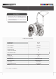
7 ■■■■■ ■■■■ ■ PARTS DIAGRAM 48 46 16 49 43 52 1 2 35 �� l��;;:jjV- 3� 21 I Parts Diagram 53
7 ■■■■■ Walk-Behind Blower » Operator's Manual PARTS LIST No. Description QTY. 4 No. Description 39 Frame Tube QTY.
■■■■■ ■ ■■■■ yardmax.com Tame the Great Outdoors* 847-327-0566 or 844-YARDMAX I info@yardmax.