
Panel Installation And Assembly Guide


YARDGARD SELECT
™
- FENCE FRAMEWORK INSTALLATION INSTRUCTIONS PAGE 3PAGE 2 YARDGARD SELECT
™
- FENCE FRAMEWORK INSTALLATION INSTRUCTIONS
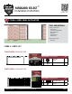
STAGE 2: FENCE PANEL INSTALLATION
2
STEP 2: INSTALLING FENCE PANELS
IMPORTANT
Fencepanelsshouldbepositionedonthe
outsideofthetensionwire.
• Unfoldonesectionoffencepanel(8´).Attachpaneltoallthree
panel-to-postbrackets.
• Liftthefencepanelsectionupintotherail.Insertapanel-to-
railclipinsidetherailconnectorcup.Makesurethetopwireis
seatedinthelipoftheclip.Lockintoplaceusingsuppliedtool.
(Fig.15)
TIP
Iffencepanelsectionsdon’talign,tappanel-to-railclips
gentlyuntilfencepanelsectionstoucheachother.
• Repeatthisprocessforeach8´section,positioningaclipinthe
centerofeach2´panel(Fig.16).Connecttwopanelstogether
byusingthreepanelclips.
• Continueinstallingin8´sectionsuntilreachingtheendofthe
fenceline.
• Hooktheterminatingpanelsectiontothethreepanel-to-post
bracketsontheterminatingpostandpulltowardtheprevious
panelsection.Iftheterminatingpanelisnotaneven2´you
willneedtocutthepanelattheclosestverticalwireusingwire
cutters.Flippanelsoshortpanelconnectstothreepost-to-
panelclips.Connectthetwopanelsectionswiththreepanel
clips.Securetheterminatingfencepaneltotoprailbyusing
panel-to-railclips.(Fig.17)
• Fastenfencepaneltoeachlinepostwithpanel-to-postclips
usingself-tappingscrews.(Fig.18)
• Fastentoprailtoeachlinepostsusingselftappingscrews
insertedfromthecurvedside.
• Attachtensionwiretofencepanelswithpanel-to-wireclipusing
adjustablepliers.Attachoneclipevery2´.
1
2
3
Near center of each mesh panel
Inside of each rail connector cup
In both ends of each sleeve
12 1 1 3 3 1 2
Cut One Panel Short
Re-Connect with
Panel Clips or Hog Rings
Pull Down
to Lock
Panel-to-Rail Clip
Unlocked
Locked
End Panel Connection
2-ft x 4-ft
Fence Panel
Cut One Panel Short
Re-Connect with
Panel Clips or Hog Rings
Pull Down
to Lock
Panel-to-Rail Clip
Unlocked
Locked
End Panel Connection
2-ft x 4-ft
Fence Panel
Fig. 15 Fence Panel Installation
Fig. 16 Locations of Panel-to-Rail Clips and
Panel Clips
Fig. 18 Fence Panel InstallationFig. 17 Terminating Panel Installation
LinePost
Cut
PanelClips
Flippanelsoshortpanelconnectsto
threepost-to-panelclips.
Overlaptheterminatingpaneltothe
lastfull8´section.
Redfencepanelrepresentstheterminatingpanel.
Self-TappingScrew
Panel-to-PostClip
Cut One Panel Short
Re-Connect with
Panel Clips or Hog Rings
Pull Down
to Lock
Panel-to-Rail Clip
Unlocked
Locked
End Panel Connection
2-ft x 4-ft
Fence Panel
RailConnector
Wire
Panel-to-Post
Bracket
Panel-to-RailClip
Panel-to-RailClipInstallation
TopRail
(CutawayView)
Locked
Pull Down
Insert
Locked
Pull Down
Insert
Locked
Pull Down
Insert
STAGE 2: FENCE PANEL INSTALLATION
2
Inserttensionwire
throughholes
STEP 1: INSTALLING TENSION WIRE
• Positionthetensionband3˝fromtheground(Fig.12).
• Attachthetensionwireratchet(includedinthePostHardware
Kit)tothetensionbandandtightencarriageboltusingan
adjustablewrench(Fig.12).
• Duplicatethisstepattheoppositecorner,end,orgatepost.
• Measurethedistancebetweenthetwopostsandadd1˝to
thatmeasurement.Cuttensionwiretosize.(Fig.13)
• Threadtensionwirethroughholeinrstratchetandwrapus-
ingadjustablewrenchmaking3to4rotations(Fig.13and14).
• Stretchtensionwiretotensionwireratchetattheoppositeend
ofthefenceline.Repeatthestepsaboveandrotateuntilwire
istight.
• Repeatforeachfenceline.
Fig. 12 Tension Band Installation
Fig. 13 Tension Wire Insertion
Fig. 14 Tighten Tension Wire
3˝
TensionBand
TensionWireRatchet
AdjustableWrench