YaRD'MaN OPERATOR'S MANUAL AutoDrive Lawn Tractor Model 604 TM IMPORTANT: Warning: READ SAFETY This unit is equipped RULES AND INSTRUCTIONS CAREFULLY with an internal combustion engine and should not be used on or near any unimproved forest- covered, brush-covered or grass-covered land unless the engine's exhaust system is equipped with a spark arrester meeting applicable local or state laws (if any). If a spark arrester is used, it should be maintained in effective working order by thoperefor.
SECTION 1: TABLE OF CONTENTS FtNDING YOUR MODEL NUMBER ....................................................... CALLING CUSTOMER SUPPORT ........................................................ IMPORTANT SAFE OPERATION PRACTICES .............................................. SAFETY LABLES FOUND ON YOUR UNIT................................................. SLOPE GAUGE ...................................................................... ATTACHMENTS & ACCESSORIES ..............................................
SECTION 4: IMPORTANT WARNING: THIS SYMBOL SAFE OPERATION PRACTICES POINTS OUT IMPORTANT SAFETY INSTRUCTIONS WHICH, IF NOT FOLLOWED, COULD ENDANGER THE PERSONAL SAFETY AND/OR PROPERTY OF YOURSELF AND OTHERS. READ AND FOLLOW ALL INSTRUCTIONS IN THIS MANUAL BEFORE ATTEMPTING TO OPERATE YOUR LAWN MOWER. FAILURE TO COMPLY WITH THESE INSTRUCTIONS MAY RESULT IN PERSONAL INJURY. WHEN YOU SEE THIS SYMBOL, HEED ITS WARNING.
• Disengage all attachment clutches, thoroughly depress the brake pedal, and shift into neutral before attempting to start engine. • Your mower is designed to cut normal residential grass of a height no more than 10". Do not attempt to mow through unusually tall, dry grass (e.g., pasture) or piles of dry leaves. Debris may build up on the mower deck or contact the engine exhaust presenting a potential fire hazard. 2.
• Keep all nuts, bolts and screws tight to be sure the equipment is in safe working condition. • • Never tamper with safety devices. Check their proper operation regularly. Use all guards as instructed in this manual. After striking a foreign object, stop the engine, remove the wire from the spark plug and thoroughly inspect the mower for any damage. Repair the damage before restarting and operating the mower.
USE THIS PAGE AS A GUIDE TO DETERMINE SLOPES SAFELY. SIGHT AND HOLD THIS LEVEL WITH A VERTICAL TREE 14 I WHERE YOU MAY NOT OPERATE A POWER POLE I A CORNER OF A BUILDING I I OR A FENCE POST I | I I I O (JD O m ,_ WARNING Do not mow on inclines with a slope in excess of 15 degrees (a rise of approximately 2-1/2 feet every 10 feet). A riding mower could overturn and cause serious injury.
SECTION 5: ATTACHMENTS MODEL NUMBER OEM-190-60t 0EM-190-602 OEM-190-112 0EM-190-118 OEM-190-603 OEM-190-604 OEM-190-822 0EM-190-823 & ACCESSORIES DESCRIPTION FastAttach- Twin Bagger Grass Collector (For 42-inch Decks Only) Fast.
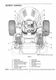
SECTION 7: CONTROLS B D I C M \ F A G J E K L -- NOTE: Steering Wheel not shown for clarity.
IGNITION IMPORTANT: When SWITCH To start the engine, insert key into the ignition switch and turn clockwise to the START position. Release key to the ON position once engine has fired. See Figure 4. Refer to STARTING THE ENGINE in the OPERATION section of this manual for detailed starting instructions. The ignition switch is also used to operate the headlights.
LIFT LEVER BRAKE The lift lever is used to change the operating position (height) of the cutting deck. To operate, move the lever to the left, then place in the notch best suited for your application. The brake pedal is located on the right front side of the tractor above the AutoDrive- pedal along the running board. The brake pedal can be used for sudden stops or setting the parking brake.
CRUISE CONTROL BU'I-rON 6 The cruise control button is located on the tractor dash panel to the left of the iBm ignition switch. Push the cruise control button while traveling forward at a desired speed. While holding the button in, release pressure from the AutoDrive,- pedal. This will engage the cruise control and allow the tractor to remain at that speed without applying pressure to the AutoDrive,- pedal. Depress the brake pedal or the AutoDdve- pedal to deactivate cruise control.
SETTING THE CUTTING HEIGHT STOPPING THE ENGINE Select the height position of the cutting deck by placing the deck lift lever in any of the six different cutting height notches on the right side of the fender. Then adjust the deck wheels so that they are at least 1/4 inch to 1/2 inch above the ground when the tractor is on a smooth, flat surface such as a driveway. Place the PTO lever in the disengaged (OFF) position from the discharge the WARNING: Keep chute hands opening and feetofaway cutting deck.
• While continuing to hold the cruise button in, lift your foot from the AutoDdve- pedal (you should feel the cruise latch engage). • If properly engaged, the cruise control button and the AutoDdve.- pedal should lock in the down position, and the tractor will maintain the same forward speed.
Do not cut the grass too short. Short grass invites weed growth and yellows quickly in dry weather. MOWING This tractor is equipped with one of MT_s high quality cutting decks. The following information will be helpful when using the cutting deck with your tractor. • Mowing should always engine at full throttle. • Do not mow at high ground speed, especially if a mulch kit or grass collector is installed. not allow anyone the area of the tractor WARNING: To in avoid possible injury, do while mowing.
• Measurethe distancefromthe outside of the left blade tip to the ground and the distance from the outside of the right blade tip to the ground. Both measurements taken should be equal. If they're not, proceed to the next step. • Loosen, but do NOT remove, the hex cap screw on the left deck hanger bracket. See Figure 7B. • Balance the deck so that both blade tip measurements taken earlier are equal. • Retighten the hex cap screw on the left deck hanger bracket when proper adjustment is achieved.
Fronttiretoe-in can be measured BRAKE as follows: • Place the steering wheel in position for straight ahead travel. Insert a 1/4" dowel up through aligning holes in both the steedng gear and support plate. See Figure 10. ADJUSTMENT If the tractor does not come to a complete stop when the brake pedal is completely depressed, or if the tractor's rear wheels can roll with the parking brake applied, the brake is in need of adjustment.
• LocatethePTO • Reinsert the Fro engagement rod into the hole in the FrO adjuster link and reinsert the cotter pin removed earlier (if undamaged). engagement rod and the PTO adjuster link by looking at the tractor's underside. See Figure 12. • Remove the cotter pin that affixes the lower end of the PTO engagement rod to the PTO adjuster link. Save the pin. See Figure 12.
CLEANING THE ENGINE • Lower the deck by moving the lift lever into the bottom notch on the right fender. AND DECK Any fuel or oil spilled on the machine should be wiped off promptly. Do NOT allow grass, leaves, and dirt to accumulate around the cooling fins of the engine or on any other part of the machine, especially the pulleys and other moving parts. Clean the underside of the deck with a wisk broom, putty knife or forced air after each mowing.
CHANGING THE DECK BELT(S) All belts on your tractor are subject to wear and should be replaced if any signs of cracking, shredding or rotting are present. IMPORTANT: The V-belts found on your tractor are specially designed to engage and disengage safely. A substitute (non-OEM) V-belt can be dangerous by not disengaging completely. For a proper working machine, use factory approved belts.
IMPORTANT: it is recommended (POWER TAKE-OFF) ADJUSTMENT that the PTO be readjusted after replacing the deck belt. Refer to PTO in the ADJUSTMENTS section of this manual for the properpmcedure. • Remount the belt guards removed earlier. PTO (Top) Belt Bottom Belt CHANGING THE TRANSMISSION 42-Inch Deck 754-0472 N/A 46-Inch Deck 754-0476 754-0349 DRIVE BELT(S) All belts on your tractor are subject to wear and should be replaced ff any signs of cracking, shredding or retting are present.
Battery Tray Opening Variable-speed Shift Lever Rear Idler Pulley • Drive belt (Lower) • Drive belt (Upper) "Z2Z2222_-_-_ Front Idler Pulley _I Belt Keeper :" :i Auto - pedal Engine Pulley Transmission NOTE: Transmission Pulley Front of Tractor View shownfrom above tractor, _,- Figure 16 • Remove the hex bolt from the center of the • Remove the rear idler pulley from the doubleidler bracket while unrouting the belt from around both the rear and the front idler pulley. Refer to Figure 16.
• Remove the two hex bolts (from both sides of the tractor) that affix the PTO actuator bracket to the tractor frame. See Figure 19.
NOTE: The hex flange nut has a right-handed thread pattern. Do NOT attempt to force the nut in the incorrect direction. Doing so may damage the nut and create a safety hazard. IMPORTANT: Use a torque wrench to tighten the blade spindle hex flange nut to between 70 footpounds and 90 foot-pounds. BATTERY _nge Nut BIo_ of-_oood The battery is sealed and is maintenance-free. levels cannot be checked. Acid • Always keep the battery cables and terminals clean and free of corrosive build-up.
TIRES The recommended operating tire pressure is approximately 10 psi for the rear tires and 14 psi for the front tires. Refer to the tire sidewall for exact tire SECTION manufacturer's recommended psi. Do not overinflate. Uneven tire pressure could cause the cutting deck to mow unevenly. 11: LUBRICATION engine before performing any WARNING: A/ways stop themaintenance.
SECTION 12: TROUBLESHOOTING Trouble Possible Cause(s) GUIDE Corrective Action There are two safety switches in the starting circuit of your unit: the brake pedal switcf and the PTO switch. Make certain the actuator is fully depressing the buttons on eact switch. The Operator must be seated on the tractor in order to start the engine, also. depressed. Battery installed The battery must be installed with negative terminal attached to black ground wire.
Model 604 .÷ 5 7 REF. PART NO. NO. 1 625-0051 725-1739 2 3 4 5 6 7 8 9 10 11 12 13 725-1649 629-0913 629-0924 710-0599 712-3006 725-1426 725-1657A 725-1741 725-1743 725-1745 726-1747 736-0222 736-0329 DESCRIPTION Bul_Socket Headlight Assembly Bulb Only Socket Only Wiring Harness Harness Adapter (for Kohler engines) Self Tapping Screw, 1/4-20 x .
Electrical System/Tractor Body 28_ 25 24 S I I 35 REF. NO. 1 2 34 5 6 7 8 9 10 11 12 13 14 15 16 17 18 19 20 PART NO. 710-0768 710-0599 710-0751 710-0895 710-0924 710-3008 '12-0292 712-3004A 712-3027 725-1649 731-1978 731-1979 731-1980 731-1981 731-1982 731-1995 731-1996 736-0173 736-3078 747-1132 DESCRIPTION Self Tapping Screw, 1/4-20 x 1.0 Self Tapping Screw, 1/4-20 x .5 Hex Cap Screw, 1/4-20 x .62 Self Tapping Screw, 1/4-15 x .75 Pan Phillips Screw, 1/4-20 x .75 Hex Cap Screw, 5/16-18 x .
Model 604 5O 2B
Lift Assembly REF. NO. t 2 3 4 5 6 7 8 9 10 11 12 13 PART NO. 647-0040 683-0197 711-0332 712-0206 712-0431 712-3004A 712-3083 714-0104 714-0111 716-0106 720-0311 732-0874 732-0934 14 15 16 17 18 19 20 21 22 23 24 25 26 736-0275 736-0921 736-3019 736-3084 738-0 138 738-0380 741-0225 741-0715 746-0968 747-1111 756-1154 783-0678 783-0720 REF. NO, 27 28 29 30 31 32 33 34 35 36 37 38 39 40 41 42 43 44 45 46 47 48 49 DESCRIPTION Deck Stabilizer Rod Lift Shaft Assembly Clevis Pin, .5 x .
Model 604 24 jJ_ 42 45 25 44 37 33 _"" 29 30 36
Steering Assembly PART NO. 683-0263 710-0604 =783-0726 783-0727 783-0728 710-0514 711-1291 711-1292 712-0240 712-0241 712-0431 712-0459 712-3004A 717-1550 717-1554 723-0448A 736-0169 736-3084 738-1001 741-0475 741-0656 748-0416 731-1869 731-1904 638-0019 638-0021 26 638-0020 638-0022 REF. NO. 1 2 3 4 5 6 7 8 9 10 11 12 13 14 15 16 17 18 19 20 21 22 23 24 25 RER NO. DESCRIPTION Lower Frame Assembly Self-tapping Screw, 5116-18 x .
Model 604 13 (3 '12 21_ •. j78 I iI r I j71 il 18., 36.., ° /281 J o 6_ I r" 35 69 38 23 68 76 52 I_ i "> J ' -.
Drive System REF. PART NO. NO.
Model 604 5 56 53 38 5 ,.
Power Take-off System REF. NO. 1 2 3 4 5 6 7 8 9 10 11 12 13 14 15 16 17 18 19 20 21 22 23 24 25 26 27 28 29 3O 31 32 PART NO. 683-0278 683-0282 710-0514 710-0597 710-0604 710-1260A 710-3011 710-3180 710-3199 712-0431 712-3004A 712-3010 712-3027 714-0111 725-1657A 731-2111 732-0977 732-0978 736-0140 736-0176 736-0272 738-1021 736-1125 741-0708 747-1112 747-1114 747-1174 748-0416 748-0421 756-0627 783-0744 783-0796 RER: NO.
Model 604 46-inch Deck ® 19 55 25 26 11 3O 17 42-inch Deck 25J26 12 13 17 36
Cutting Decks :IEF. PART NO. NO. 1 17982 2 618-O240 756*0969 3 618-0241 756*0603 4 683*0254 5 683-0265 6 710-0167 7 710-0347 8 710-0514 9 710-0528 10 710-0599 11 710-0650 12 710-0751 13 710-1260A 14 712-3288 15 712-0241 16 712.0291 17 712-0417A 18 712-O431 19 712-3027 20 714-0104 21 717-1553 22 731-1032A 23 732-0306 24 732-0594A 25 734-0973 26 736-0105 27 736-0119 28 738-0347 29 738-0373 30 742-0611 IER _10. 31 32 33 34 35 36 37 38 39 40 41 DESCRIPTION Reinforcement Spindle Plate Spindle Assembly, 5 Dia.
Model 604 (d_ector must face forward) Kohler Single-cylinder (deflectormust face Ion_rd) 38
Engine Accessories Briggs & Stratton Intek Single 18 RER NO. 1 2 3 4 5 6 7 8 9 10 11 12 13 14 15 16 17 18 PART NO. 710-0148 710-0599 710-0604 710-1237 710-1314 710-1315 712-0798 ,721-0460 726-0205 736-0 119 736-0221 751 B221535 751-0535 751-0564 751-0616 751-0650 751-0651 751-3140 _EF. NO. 19 20 21 22 23 24 25 26 27 28 29 30 31 32 33 34 35 36 DESCRIPTION Self Tapping Screw, #8-32 x .375 Serf Tapping Screw, 1/4-20 x .5 : Self Tapping Screw, 5/16-18 x .625 Screw, #10-32 x .